Advertisement
Quick Links
November, 2022
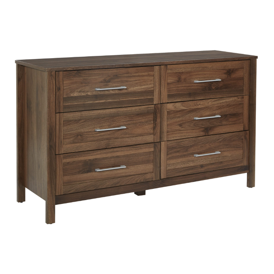
SK6DRD
6 DRAWER DRESSER
Assembly Instructions - Important:
Carefully unpack and identify each component before attempting to assemble. Refer to parts list. Please take care when
assembling the unit and always set the parts on a clean, soft surface. If you require any assistance with assembly, parts or
information on other products, please visit our website: www.officestar.net or call or write us.
Advertisement

Related Manuals for OSP Home Furnishings SK6DRD


Summary of Contents for OSP Home Furnishings SK6DRD
- Page 1 November, 2022 SK6DRD 6 DRAWER DRESSER Assembly Instructions - Important: Carefully unpack and identify each component before attempting to assemble. Refer to parts list. Please take care when assembling the unit and always set the parts on a clean, soft surface. If you require any assistance with assembly, parts or...
- Page 2 1-800-950-7262, Monday through Friday 8:00 a.m. - 3:30 p.m. Pacific Time. To make a warranty claim, contact Parts Department. Provide model number, proof of purchase, description of the problem and obtain return authorization. At its option OSP Home Furnishings will: ®...
- Page 3 PARTS (1) Table Top (1 PC) (2) Front Horizontal Frame (1 PC) (carton #1 of 2) (carton #1 of 2) (4) Bottom Frame (1 PC) (3) Rear Horizontal Frame (1 PC) (carton #2 of 2) (carton #1 of 2) (6) Left Side Panel (1 PC) (5) Right Side Panel (1 PC) (carton #2 of 2) (carton #2 of 2)
- Page 4 PARTS (13) Right Horizontal Frame (2 PCS) (14) Left Horizontal Frame (2 PCS) (carton #1 of 2) (carton #1 of 2) (16) Rear Top Panel (1 PC) (15) Center Leg (1 PC) (carton #1 of 2) (carton #1 of 2) (18) Right Drawer Front (3 PCS) (17) Rear Bottom Panel (1 PC) (carton #2 of 2)
-
Page 5: Hardware List
HARDWARE LIST (located in carton #1 of 2) DRAWING DESCRIPTION SIZE QUANTITY Cam Bolt Ø7 x 32mm 77 PCS Cam Lock Ø15 x 10mm 90 PCS Plastic Cap Ø17.5mm 31 PCS Dowel Ø6 x 30mm 86 PCS Joint Cam Bolt Ø7 x 41mm 13 PCS Joint Cam Nut... - Page 6 HARDWARE LIST (located in carton #1 of 2) DRAWING DESCRIPTION SIZE QUANTITY Drawer Glides 21 x 350mm 6 PCS Sticker Cover Ø25mm 4 PCS Anchor Ø6 x 40mm 2 PCS Screw Ø6 x 37mm 2 PCS SIZING REFERENCE GUIDE TOOLS REQUIRED FOR ASSEMBLY (NOT PROVIDED)
- Page 7 CAM LOCK INSTALLATION When inserting Cam Locks, please be sure notch is facing corresponding hole. This will ensure easy fastening.
- Page 8 STEP 1 Ø6 X 9 mm FULLY TIGHTEN ALL CAM BOLTS (A), SCREWS (H) & SECURELY FASTEN ALL CAM LOCKS (B) STEP 2 FULLY TIGHTEN ALL CAM BOLTS (A)
- Page 9 STEP 3 FULLY TIGHTEN ALL SCREWS (G) & SECURELY FASTEN ALL CAM LOCKS (B) STEP 4...
- Page 10 STEP 5 FULLY TIGHTEN ALL SCREWS (G) STEP 6 FULLY TIGHTEN ALL JOINT CAM BOLTS (E)
- Page 11 STEP 7 SECURELY FASTEN ALL CAM LOCKS (B) STEP 8 Ø6 X 52 mm FULLY TIGHTEN ALL SCREWS (G)
- Page 12 STEP 9 FULLY TIGHTEN ALL CAM BOLTS (A & E) STEP 10 FULLY TIGHTEN ALL CAM BOLTS (A)
- Page 13 STEP 11 SECURELY FASTEN ALL CAM LOCKS (B) STEP 12 Ø6 X 9 mm FULLY TIGHTEN ALL SCREWS (H)
- Page 14 STEP 13 SECURELY FASTEN ALL CAM LOCKS (B) STEP 14 SECURELY FASTEN ALL CAM LOCKS (B)
- Page 15 STEP 15 FULLY TIGHTEN ALL CAM BOLTS (A) STEP 16 SECURELY FASTEN ALL CAM LOCKS (B)
- Page 16 STEP 17 FULLY TIGHTEN ALL CAM BOLTS (A) & SCREWS (K) STEP 18 Ø6 X 52 mm FULLY TIGHTEN ALL SCREWS (G) & SECURELY FASTEN ALL CAM LOCKS (B)
- Page 17 STEP 19 Ø6 X 52 mm FULLY TIGHTEN ALL SCREWS (G) & SECURELY FASTEN ALL CAM LOCKS (B) STEP 20 Ø6 X 12 mm Ø6 X 19 mm FULLY TIGHTEN ALL SCREWS (I & O)
- Page 18 STEP 21 Ø6 X 9 mm FULLY TIGHTEN ALL SCREWS (H) STEP 22 Ø 6 x 19 mm FULLY TIGHTEN ALL SCREWS (Q)
-
Page 19: Anti-Tip Kit Installation
ANTI-TIP KIT INSTALLATION Place product in desired location. Mark location of pilot holes. Carefully drill one 6mm pilot hole into wall for each Support Bracket (P). Gently tap one Anchor (U) into each pilot hole. Secure Support Brackets (P) to wall using one Screw (V) for each Support Bracket (P). FULLY TIGHTEN SCREWS USING PHILLIPS SCREWDRIVER (not provided).
Need help?
Do you have a question about the SK6DRD and is the answer not in the manual?
Questions and answers