Advertisement
October, 2019
SRA07
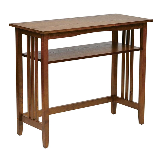
SIERRA FOYER TABLE
Assembly Instructions - Important:
Carefully unpack and identify each component before attempting to assemble. Refer to parts list. Please take care when
assembling the unit and always set the parts on a clean, soft surface. If you require any assistance with assembly, parts or
information on other products, please visit our website: www.officestar.net or call or write us.
Advertisement
Table of Contents

Related Manuals for OSP Home Furnishings SIERRA SRA07


Summary of Contents for OSP Home Furnishings SIERRA SRA07
- Page 1 October, 2019 SRA07 SIERRA FOYER TABLE Assembly Instructions - Important: Carefully unpack and identify each component before attempting to assemble. Refer to parts list. Please take care when assembling the unit and always set the parts on a clean, soft surface. If you require any assistance with assembly, parts or information on other products, please visit our website: www.officestar.net or call or write us.
- Page 2 LIMITED WARRANTY OSP Home Furnishings™ warrants to the original purchaser that this product will be free from defects in material and workmanship as described below. OSP Home Furnishings™ will repair or replace, at its option, without charge to the original purchaser only, defective products or parts for one (1) year from the date of purchase.
- Page 3 3. Rename all English discriptions to French discriptions. PARTS (A) Top Panel (1 PC) (B) Shelf (1 PC) (C) Left & Right Side Frame (2 PCS) (D) Top Crossbar (2 PCS) (E) Rear Crossbar (1 PC)
- Page 4 HARDWARE LIST DRAWING DESCRIPTION SIZE QUANTITY Bolt 1/4” x 30mm 4 PCS Bolt 1/4” x 60mm 2 PCS Cam Screw 6.5 x 35mm 8 PCS Cam Nut 15 x 12.5mm 8 PCS Barrel Nut (1/4”) 9 x 12.5mm 2 PCS Wood Plug 13 x 8mm 2 PCS...
- Page 5 STEP 1 (CL) DO NOT FULLY TIGHTEN BOLTS. FULLY TIGHTEN CAM SCREWS (3) AND CAM NUTS (4) USING PHILLIPS SCREWDRIVER (NOT PROVIDED.) STEP 2 (CR) DO NOT FULLY TIGHTEN BOLTS. FULLY TIGHTEN CAM SCREWS (3) AND CAM NUTS (4) USING PHILLIPS SCREWDRIVER (NOT PROVIDED.)
- Page 6 STEP 3 TURN TO THE UPRIGHT POSITION, APPLY FIRM PRESSURE TO ALIGN & FULLY TIGHTEN ALL BOLTS USING ALLEN WRENCH (7). FULLY TIGHTEN CAM SCREWS (3) AND CAM NUTS (4) USING PHILLIPS SCREWDRIVER (NOT PROVIDED.)
Need help?
Do you have a question about the SIERRA SRA07 and is the answer not in the manual?
Questions and answers