Advertisement
Quick Links
August, 2019
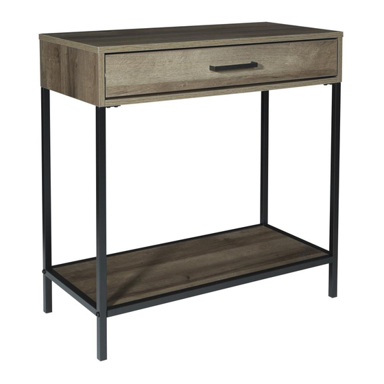
BRY507
BRAYDON FOYER TABLE
Assembly Instructions - Important:
Carefully unpack and identify each component before attempting to assemble. Refer to parts list. Please take care when
assembling the unit and always set the parts on a clean, soft surface. If you require any assistance with assembly, parts or
information on other products, please visit our website: www.officestar.net or call or write us.
Advertisement

Related Manuals for OSP Home Furnishings BRY507


Summary of Contents for OSP Home Furnishings BRY507
- Page 1 August, 2019 BRY507 BRAYDON FOYER TABLE Assembly Instructions - Important: Carefully unpack and identify each component before attempting to assemble. Refer to parts list. Please take care when assembling the unit and always set the parts on a clean, soft surface. If you require any assistance with assembly, parts or...
- Page 2 LIMITED WARRANTY OSP Home Furnishings™ warrants to the original purchaser that this product will be free from defects in material and workmanship as described below. OSP Home Furnishings™ will repair or replace, at its option, without charge to the original purchaser only, defective products or parts for one (1) year from the date of purchase.
- Page 3 PARTS (A) Top Panel (1 PC) (B) Left Side Panel (1 PC) (C) Right Side Panel (1 PC) (D) Back Panel (1 PC) (E) Front Support (1 PC) (F) Rear Support (1 PC) (G) Shelf (1 PC) (H) Side Frame (2 PCS) (I) Support (2 PCS) (J) Drawer Front Panel (1 PC)
- Page 4 PARTS (K) Drawer Left Side Panel (1 PC) (L) Drawer Right Side Panel (1 PC) (M) Drawer Rear Panel (1 PC) (N) Drawer Support (1 PC) (O) Drawer Bottom Panel (1 PC) CAM LOCK INSTRUCTIONS 180°...
-
Page 5: Hardware List
HARDWARE LIST DRAWING DESCRIPTION SIZE QUANTITY Screw #6 x 1/2” 10 PCS + 2 EXTRA Screw #8 x 1/2” 6 PCS + 1 EXTRA Screw 6 x 14mm 8 PCS + 1 EXTRA Screw M4 x 22mm 2 PCS Screw #10 x 1-1/2”... -
Page 6: Drawer Installation
DRAWER INSTALLATION If you need to remove the drawer with ball bearing slides from the unit, follow the steps below to prevent any damage to the slides or the drawer. If you need to remove the drawer, please pull the drawer all the way out, then push the plastic release lever of the ball bearing slide up on one side and down on the other side, and then pull the drawer completely out. - Page 7 STEP 1 FULLY TIGHTEN ALL LARGE CAM SCREWS (8) USING PHILLIPS SCREWDRIVER (NOT PROVIDED). STEP 2 (14 Rail) (14 Slide) (14 Rail) (11) FULLY TIGHTEN ALL LARGE CAM SCREWS (8) AND SCREWS (1) USING PHILLIPS SCREWDRIVER (NOT PROVIDED).
- Page 8 STEP 3 (11) FULLY TIGHTEN ALL SCREWS (5) USING PHILLIPS SCREWDRIVER (NOT PROVIDED). STEP 4 (10) FULLY TIGHTEN ALL LARGE CAM NUTS (10) USING PHILLIPS SCREWDRIVER (NOT PROVIDED).
- Page 9 STEP 5 DO NOT FULLY TIGHTEN SCREWS (2). STEP 6 (15) DO NOT FULLY TIGHTEN BOLTS (6).
- Page 10 STEP 7 FULLY TIGHTEN ALL SCREWS USING PHILLIPS SCREWDRIVER (NOT PROVIDED). FULLY TIGHTEN ALL BOLTS (6) USING ALLEN WRENCH (15). STEP 8 (10) FULLY TIGHTEN ALL LARGE CAM NUTS (10) USING PHILLIPS SCREWDRIVER (NOT PROVIDED).
- Page 11 STEP 9 (14 Slide) FULLY TIGHTEN ALL SCREWS (1) USING PHILLIPS SCREWDRIVER (NOT PROVIDED). STEP 10 (13) FULLY TIGHTEN ALL SCREWS (4) AND SMALL CAM SCREWS (7) USING PHILLIPS SCREWDRIVER (NOT PROVIDED).
- Page 12 STEP 11 (12) FULLY TIGHTEN ALL SMALL CAM NUTS (9) USING PHILLIPS SCREWDRIVER (NOT PROVIDED). STEP 12...
- Page 13 STEP 13 FULLY TIGHTEN ALL SCREWS (5) USING PHILLIPS SCREWDRIVER (NOT PROVIDED). STEP 14...
Need help?
Do you have a question about the BRY507 and is the answer not in the manual?
Questions and answers