Table of Contents
Advertisement
Quick Links
October, 2019
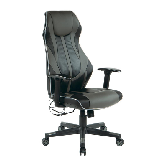
GIG25
GIGABYTE GAMING CHAIR
Assembly Instructions - Important:
Carefully unpack and identify each component before attempting to assemble. Refer to parts list. Please take care when
assembling the unit and always set the parts on a clean, soft surface. If you require any assistance with assembly, parts or
information on other products, please visit our website: www.officestar.net or call or write us.
Advertisement
Table of Contents

Related Manuals for OSP Home Furnishings GIG25


Summary of Contents for OSP Home Furnishings GIG25
- Page 1 October, 2019 GIG25 GIGABYTE GAMING CHAIR Assembly Instructions - Important: Carefully unpack and identify each component before attempting to assemble. Refer to parts list. Please take care when assembling the unit and always set the parts on a clean, soft surface. If you require any assistance with assembly, parts or...
- Page 2 At its option OSP Home Furnishings will: (a) Supply compatible components of current manufacture. (b) Repair the customer’s component. The customer must prepay freight on any components returned to the factory. Return freight on components still in warranty will be paid by OSP Home Furnishings.
- Page 3 3. Rename all English discriptions to French discriptions. PARTS (A) Base (1 PC) (B) Caster (5 PCS) (C) Pneumatic Cylinder (1 PC) (D) Bellows (1 PC) (E) Seat Plate (1 PC) (F) Left and Right Arm (2 PCS) (G) Backrest (1 PC) (H) Seat Cushion (1 PC) (I) Power Adapter (1 PC)
- Page 4 HARDWARE LIST DRAWING DESCRIPTION QUANTITY Bolt 3 PCS Bolt 8 PCS Bolt 2 PCS Allen Wrench 1 PC...
- Page 5 STEP 1 INSERT FIVE CASTERS (B) INTO BASE (A), PUSH HARD UNTIL YOU FEEL OR HEAR THE CASTER (B) SNAP INTO PLACE. INSERT PNEUMATIC CYLINDER (C) INTO BASE (A) AND SLIP BELLOWS (D) OVER PNEUMATIC CYLINDER (C). STEP 2 ATTACH SEAT PLATE (E) TO SEAT CUSHION (H) WITH THE ARROW TOWARDS THE FRONT OF THE CHAIR USING TWO BOLTS (3) FOR FRONT HOLES AND TWO BOLTS (2) FOR REAR HOLES.
- Page 6 STEP 3 ATTACH BACKREST (G) TO REAR OF SEAT CUSHION (H) USING THREE BOLTS (1). FULLY TIGHTEN BOLTS (1). STEP 4 (FL) (FR) ATTACH ARMS (FL & FR) TO SEAT CUSHION (H) USING THREE BOLTS (2) FOR EACH ARM (F), FULLY TIGHTEN BOLTS (2).
- Page 7 STEP 5 PLACE THE ASSEMBLED SEAT ON TOP OF PNEUMATIC CYLINDER (C) AND APPLY DOWNWARD PRESSURE. STEP 6 CONNECT CORDS B TO C AND D TO E. CONNECT POWER ADAPTER (I) TO CORD A.
Need help?
Do you have a question about the GIG25 and is the answer not in the manual?
Questions and answers