Advertisement
www.ti.com
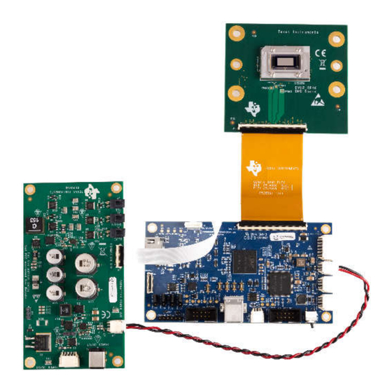
EVM User's Guide: DLP4620SQ1EVM DLP4621Q1EVM
DLP4620SQ1EVM and DLP4621Q1EVM Evaluation Module
Description
The DLP4620SQ1EVM Evaluation Module (EVM) is
a complete electronic subsystem designed to control
the DLP4620S-Q1, DLPC231S-Q1, and TPS99000S-
Q1 devices, which support RGB display applications
such as augmented reality head-up displays.
The DLP4621Q1EVM EVM is designed to control
the DLP4621-Q1, DLPC231-Q1, and TPS99001-Q1,
which support monochrome applications such as
high-resolution headlights.
There are no optical elements provided with this EVM,
except for the DMD. Expect that this EVM is procured
to mount to a custom-designed picture generation unit
(PGU) or projector.
Features
•
DLP4620S-Q1 DMD board with RGB display
LED driver and DLPC231S-Q1 DMD controller for
DLP4620SQ1EVM kit
•
DLP4621-Q1 DMD board with Headlight LED
driver and DLPC231-Q1 DMD controller for
DLP4621Q1EVM kit
•
600MHz SubLVDS DMD interface for low power
and emission
DLP4620SQ1EVM
DLPU137 – APRIL 2024
Submit Document Feedback
•
DMDs have 0.46-inch diagonal micromirror array
– 7.6µm micromirror pitch
– ±12° micromirror tilt angle
– Bottom illumination enables high efficiency and
– 10kHz DMD refresh rates over temperature
– Compatible with LED or laser illumination
•
Video input interface on controller board
– Single OpenLDI (FPD-Link I) port up to 110MHz
– 24-bit RGB parallel interface up to 110MHz
•
Configurable host interface
– I2C (400kHz)
– SPI (10MHz)
Applications
•
Augmented reality head-up display (AR HUD)
•
Transparent window display
•
Adaptive driving beams, glare-free beam steering,
reflective traffic sign and pedestrian dimming,
symbol projection
Copyright © 2024 Texas Instruments Incorporated
smaller engine size
extremes
DLP4621Q1EVM
DLP4620SQ1EVM and DLP4621Q1EVM Evaluation Module
Description
1
Advertisement
Table of Contents

Related Manuals for Texas Instruments DLP4620SQ1EVM


Summary of Contents for Texas Instruments DLP4620SQ1EVM
- Page 1 • DMDs have 0.46-inch diagonal micromirror array Description – 7.6µm micromirror pitch The DLP4620SQ1EVM Evaluation Module (EVM) is – ±12° micromirror tilt angle a complete electronic subsystem designed to control – Bottom illumination enables high efficiency and the DLP4620S-Q1, DLPC231S-Q1, and TPS99000S-...
-
Page 2: Kit Contents
EVMs. 1.2 Kit Contents The DLP4620SQ1EVM consists of a DLPC231S-Q1 DMD controller board, a DLP4620S-Q1 DMD board, an LED driver board, and cables. Similarly, the DLP4621Q1EVM consists of the DLPC231-Q1 DMD controller board, a DLP4621-Q1 DMD board , an LED driver board, and cables. - Page 3 –25 2.5X5.5mm SOLDER The DLP4620SQ1EVM is not a production design and is intended for evaluation only. 1.3.3 Component Temperature Ratings - DLP4621Q1EVM The PCB materials and most of the PCB components are rated to operate between –40°C to 105°C, including the DLP4621-Q1, the DLPC231-Q1, and the TPS99000-Q1.
- Page 4 C Timing For more information on SPI and I C specifications, see the DLPC231S-Q1 data sheet (DLPS201) or the DLPC231-Q1 (DLPS054) data sheet. DLP4620SQ1EVM and DLP4621Q1EVM Evaluation Module DLPU137 – APRIL 2024 Submit Document Feedback Copyright © 2024 Texas Instruments Incorporated...
-
Page 5: Device Information
Evaluation Module Overview 1.4 Device Information The DLP4620SQ1EVM kit contains the electronics required to drive a DLP4620S-Q1 DMD board for HUD applications while the DLP4621Q1EVM kit contains the electronics to drive a DLP4621-Q1 DMD board for headlight applications. The DLP4620SQ1EVM offers interface options for I2C, SPI, and USB. -
Page 6: Controller Pcb
EVMs. Some features include flashing new firmware onto the controller, changing test pattern generator (TPG) images, changing sources (such as TPG to HDMI), or obtaining controller or PMIC (TPS99000- Q1) diagnostics. DLP4620SQ1EVM and DLP4621Q1EVM Evaluation Module DLPU137 – APRIL 2024 Submit Document Feedback... - Page 7 On the opposite side of the EVM is a HUD interface port, which helps control and monitor an illumination design such as the RGB LED driver provided in the kit. This is used for the DLP4620SQ1EVM. Figure 2-3. DLPC231SQ1EVM Controller PCB...
- Page 8 Off: Do not hold in boot (continue to main application) On: Hold in boot PROJ_ON Off: Turn off system On: Turn on system DLP4620SQ1EVM and DLP4621Q1EVM Evaluation Module DLPU137 – APRIL 2024 Submit Document Feedback Copyright © 2024 Texas Instruments Incorporated...
- Page 9 2.4 RGB LED Driver PCB - DLP4620SQ1 The DLP4620SQ1EVM can operate as a standalone system with just the controller board and the DMD board, but the EVM can be combined with an RGB LED design. The LED driver board shown in...
- Page 10 PIN3 Pre-regulated drive voltage (6.5V or 8V) Feedback voltage connection Feedback voltage connection Pre-regulator feedback voltage for 6.5V drive for 8V drive DLP4620SQ1EVM and DLP4621Q1EVM Evaluation Module DLPU137 – APRIL 2024 Submit Document Feedback Copyright © 2024 Texas Instruments Incorporated...
- Page 11 Hardware 2.5 Cables - DLP4620SQ1EVM The DLP4620SQ1EVM kit contains the cables and Cheetah USB to SPI adapter listed in Table 2-6 and shown in Figure 2-5. Figure 2-5. DLP4620SQ1EVM Cables Table 2-6. DLP4620SQ1EVM Cables NAME REFERENCE QUANTITY Photodiode cable...
- Page 12 LED drivers (J7, J8, J9) can produce high currents up to 8A. Do not remove these headers, and do not touch the contact points during operation! Figure 2-6. LED Driver PCB - DLP4621Q1EVM DLP4620SQ1EVM and DLP4621Q1EVM Evaluation Module DLPU137 – APRIL 2024 Submit Document Feedback...
- Page 13 Figure 2-7. DLP4621-Q1 Electronics EVM LED Driver Board Timing Specifications Table 2-9. LED Driver Board Timing Specifications Parameter Value < 50μs < 2μs minimum = 1μs DLPU137 – APRIL 2024 DLP4620SQ1EVM and DLP4621Q1EVM Evaluation Module Submit Document Feedback Copyright © 2024 Texas Instruments Incorporated...
- Page 14 Host SPI cable Controller to DMD flex cable Open LDI flex cable A block diagram of the DLP4621Q1EVM can be found in Figure 2-2. DLP4620SQ1EVM and DLP4621Q1EVM Evaluation Module DLPU137 – APRIL 2024 Submit Document Feedback Copyright © 2024 Texas Instruments Incorporated...
- Page 15 Hardware 2.9 Optical Engine Requirements The DLP4620SQ1EVM can be coupled to an optical engine (not included) to implement a head-up display function or an automotive interior projection system. The detailed requirements of the optical engine are beyond the scope of this document, but the optical engine must have separate red, green and blue illuminators. These are typically LEDs.
- Page 16 3.2 Quick Start - DLP4620SQ1EVM Use the following instructions to set up the DLP4620SQ1EVM and PC. 3.2.1 Kit Assembly Instructions - DLP4620SQ1EVM An example image of the DLP4620SQ1EVM without a power supply and optics is shown in Figure 3-1. 1. Connect the DMD Flex Cable to the controller PCB (J1) and the DMD PCB (J1). Pin 1 is marked on the DMD flex cable.
- Page 17 3.3 Quick Start - DLP4621Q1EVM Use the following instructions to set up the DLP4621Q1EVM and PC. 3.3.1 Kit Assembly Instructions - DLP4621Q1EVM An example image of the DLP4620SQ1EVM without a power supply and optics is shown in Figure 3-2. 1. Connect the DMD Flex Cable to the controller PCB (J1) and the DMD PCB (J1). Pin 1 is marked on the DMD flex cable.
- Page 18 A controller PCB LED indicator (D5) illuminates green. 3.3.3 Steps to Reprogram the Onboard Flash Memory The DLP4620SQ1EVM and DLP4621Q1EVMQ1EVM come with onboard serial Flash that is pre-programed with software and basic configuration. The software and configuration can be updated by reprogramming the serial flash with the DLPC230-Q1 Automotive Control Program.
- Page 19 3-3). Note, the Cheetah must be connected to computer with USB cable for the Cheetah to show up in the drop-down menu. Figure 3-3. Connecting to the DLPC230-Q1 Using the DLPC230-Q1 Automotive Control Program DLPU137 – APRIL 2024 DLP4620SQ1EVM and DLP4621Q1EVM Evaluation Module Submit Document Feedback Copyright © 2024 Texas Instruments Incorporated...
- Page 20 4. The "Connection" Settings can be left the same way they were previously for SPI communication. 5. Click the Connect button. The green circle next to the Connect button then lights up to indicate that connection was successful to USB. DLP4620SQ1EVM and DLP4621Q1EVM Evaluation Module DLPU137 – APRIL 2024 Submit Document Feedback...
-
Page 21: Additional Information
Design Files. 4.3 Bill of Materials (BOM) The bill of materials for the DLP4620SQ1EVM are available for download on the product page of the EVM: DLP4620SQ1EVM Design Files. The bill of materials for the DLP4621Q1EVM are available for download on the product page of the EVM: DLP4621Q1EVM Design Files. - Page 22 TI products. TI’s provision of these resources does not expand or otherwise alter TI’s applicable warranties or warranty disclaimers for TI products. TI objects to and rejects any additional or different terms you may have proposed. IMPORTANT NOTICE Mailing Address: Texas Instruments, Post Office Box 655303, Dallas, Texas 75265 Copyright © 2024, Texas Instruments Incorporated...
Need help?
Do you have a question about the DLP4620SQ1EVM and is the answer not in the manual?
Questions and answers