
Related Manuals for Texas Instruments UCC25640EVM-020


Summary of Contents for Texas Instruments UCC25640EVM-020
- Page 1 UCC25640EVM-020 Evaluation Module User's Guide Literature Number: SLUUBX3B June 2019 – Revised November 2019...
- Page 2 Any other use and/or application are strictly prohibited by Texas Instruments. If you are not suitable qualified, you should immediately stop from further use of the HV EVM.
- Page 3 EVM in an adequate lucent plastic box with interlocks from accidental touch. Limitation for safe use: EVMs are not to be used as all or part of a production unit. SLUUBX3B – June 2019 – Revised November 2019 Submit Documentation Feedback Copyright © 2019, Texas Instruments Incorporated...
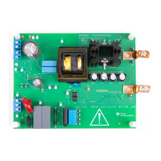
- Page 4 UCC25640EVM-020 Evaluation Module Introduction The purpose of the UCC25640EVM-020 (EVM) is to aid in evaluation of the UCC256403 and UCC256404 LLC resonant controller. The EVM is a stand-alone LLC resonant half-bridge DC-DC power converter designed to operate with DC input from 365 VDC to 410 VDC, AC input from 85 to 265 V , 47 to 63 Hz, and a nominal output of 12 VDC up to 180-W.
- Page 5 Replace R37 with 124kΩ • Connect TP1 to TP14 • Disconnect the AC voltage source Using the EVM with UCC256403 UCC25640EVM-020 comes populated with UCC256404. To use this EVM with UCC256403: • Replace U4 with UCC256403 • Remove R5 and R28 •...
- Page 6 Using the EVM with UCC24624 Synchronous Rectifier Controller UCC25640EVM-020 is delivered using the diode rectifier at the output. The option to evaluate the converter with synchronous rectification (SR) is available to the user. SR is often used to increase efficiency by replacing the freewheeling diode with a lower loss FET.
- Page 7 390 VDC and full load = 15 A mVpp SYSTEM CHARACTERISTICS Resonant frequency Peak efficiency 390 VDC, load = 8 A Operating temperature Natural convection ºC SLUUBX3B – June 2019 – Revised November 2019 UCC25640EVM-020 Evaluation Module Submit Documentation Feedback Copyright © 2019, Texas Instruments Incorporated...
- Page 8 Schematic Diagram www.ti.com Schematic Diagram Figure 3. UCC25640EVM-020 Power Stage Schematic UCC25640EVM-020 Evaluation Module SLUUBX3B – June 2019 – Revised November 2019 Submit Documentation Feedback Copyright © 2019, Texas Instruments Incorporated...
- Page 9 Schematic Diagram www.ti.com Figure 4. UCC25640EVM-020 Control Schematic SLUUBX3B – June 2019 – Revised November 2019 UCC25640EVM-020 Evaluation Module Submit Documentation Feedback Copyright © 2019, Texas Instruments Incorporated...
- Page 10 Recommended Wire Gauge: Capable of 25 A, or better than #14 AWG, with the total length of wire less than 8 feet (4 feet input and 4 feet return). UCC25640EVM-020 Evaluation Module SLUUBX3B – June 2019 – Revised November 2019 Submit Documentation Feedback Copyright © 2019, Texas Instruments Incorporated...
- Page 11 Test Setup www.ti.com Recommended Test Setup Figure 5. UCC25640EVM-020 Test Setup Diagram WARNING High voltages that may cause injury exist on this evaluation module (EVM). Please ensure all safety procedures are followed when working on this EVM. Never leave a powered EVM unattended.
- Page 12 Test Setup www.ti.com Power Factor Correction (PFC) Boost Front End Setup UCC25640EVM-020 is typical for a two stage AC/DC power supply with a PFC boost converter in front of it. The following steps and schematic describe how to connect the UCC28056EVM-296 UCC28064EVM-004, Transition-Mode (TM) PFC Controllers, to this EVM.
- Page 13 Input voltage return terminal AC Input 3-pin, AC power input, 85–265 V VOUT Output voltage positive terminal SGND Output voltage ground terminal SLUUBX3B – June 2019 – Revised November 2019 UCC25640EVM-020 Evaluation Module Submit Documentation Feedback Copyright © 2019, Texas Instruments Incorporated...
- Page 14 3. Shut down the electronic load. WARNING High voltage may still be present on the resonant capacitors after turning off the DC source. UCC25640EVM-020 Evaluation Module SLUUBX3B – June 2019 – Revised November 2019 Submit Documentation Feedback Copyright © 2019, Texas Instruments Incorporated...
- Page 15 Performance Data and Typical Characteristic Curves www.ti.com Performance Data and Typical Characteristic Curves UCC25640EVM-020 Standalone Standby and Light Load Power Table 4 lists the total standby and light load power measurement for the standalone EVM. The average input power is measured over a two minute interval.
- Page 16 Performance Data and Typical Characteristic Curves www.ti.com 9.2.2 PFC LLC Standby Power and Light Load Efficiency PFC LLC system standby power for UCC25640EVM-020 is measured with both UCC28056EVM-296 and UCC28064EVM-004. Refer to Section 5.3 for test setup and procedure. The WT310 power analyzer is used for PFC LLC standby and light load measurements.
- Page 17 Figure 9. Load Regulation vs Output Current Switching Frequency Figure 10 illustrates the converter switching frequency versus output current. Figure 10. Switching Frequency vs Output Current SLUUBX3B – June 2019 – Revised November 2019 UCC25640EVM-020 Evaluation Module Submit Documentation Feedback Copyright © 2019, Texas Instruments Incorporated...
- Page 18 5 mm above the transformer. Figure 11. Audible Noise Measurement at 10 mA Load Figure 12. Audible Noise Measurement at 20 mA Load UCC25640EVM-020 Evaluation Module SLUUBX3B – June 2019 – Revised November 2019 Submit Documentation Feedback Copyright © 2019, Texas Instruments Incorporated...
- Page 19 Figure 13. No Load (0 A) Startup (Ch2 = V ; Ch3 = LO) Figure 14. Full Load (15 A) Startup (Ch2 = V ; Ch3 = LO) SLUUBX3B – June 2019 – Revised November 2019 UCC25640EVM-020 Evaluation Module Submit Documentation Feedback Copyright © 2019, Texas Instruments Incorporated...
- Page 20 Table 8. Component Temperature Component Temperature (°C) U4 (Bx1) 42.3°C Q1 (Bx2) 44.9°C Q3 (Bx3) 46.1°C R9, R12 (Bx4) 72.2°C UCC25640EVM-020 Evaluation Module SLUUBX3B – June 2019 – Revised November 2019 Submit Documentation Feedback Copyright © 2019, Texas Instruments Incorporated...
- Page 21 Figure 17. No Load (0 A) Output Ripple (Ch2 = V Figure 18. Full Load (15 A) Output Ripple (Ch2 = V SLUUBX3B – June 2019 – Revised November 2019 UCC25640EVM-020 Evaluation Module Submit Documentation Feedback Copyright © 2019, Texas Instruments Incorporated...
- Page 22 AC Coupled; Ch4 = I Figure 20. 10 mA to 15 A Transient (Ch2 = V DC Coupled; Ch4 = I UCC25640EVM-020 Evaluation Module SLUUBX3B – June 2019 – Revised November 2019 Submit Documentation Feedback Copyright © 2019, Texas Instruments Incorporated...
- Page 23 The following plot shows the loop response with 115 VAC, 60 Hz applied to the AC input and 390 VDC applied to the DC input at full load condition. Figure 21. Bode Plot at 15 A Load SLUUBX3B – June 2019 – Revised November 2019 UCC25640EVM-020 Evaluation Module Submit Documentation Feedback Copyright © 2019, Texas Instruments Incorporated...
- Page 24 Figure 22. Steady State Waveforms at No Load (Ch2 = VCR; Ch3 = LO; Ch4 = IResonant) Figure 23. Steady State Waveforms at 15 A Load (Ch2 = VCR; Ch3 = LO; Ch4 = IResonant) UCC25640EVM-020 Evaluation Module SLUUBX3B – June 2019 – Revised November 2019 Submit Documentation Feedback Copyright © 2019, Texas Instruments Incorporated...
- Page 25 265 VAC input. 390 VDC is applied to the DC input and the output is unloaded. Figure 24. X-Cap Discharge (Ch1 = Voltage across X-Cap, C40 and C41) SLUUBX3B – June 2019 – Revised November 2019 UCC25640EVM-020 Evaluation Module Submit Documentation Feedback Copyright © 2019, Texas Instruments Incorporated...
- Page 26 Assembly Drawing and List of Materials www.ti.com Assembly Drawing and List of Materials 10.1 Assembly Drawing Figure 25. UCC25640EVM-020 Top Layer Assembly Drawing (Top view) Figure 26. UCC25640EVM-020 Bottom Layer Assembly Drawing (Top view) UCC25640EVM-020 Evaluation Module SLUUBX3B – June 2019 – Revised November 2019 Submit Documentation Feedback Copyright ©...
- Page 27 Assembly Drawing and List of Materials www.ti.com Figure 27. UCC25640EVM-020 Top Copper Assembly Drawing (Top view) Figure 28. UCC25640EVM-020 Bottom Copper Assembly Drawing (Top view) SLUUBX3B – June 2019 – Revised November 2019 UCC25640EVM-020 Evaluation Module Submit Documentation Feedback Copyright © 2019, Texas Instruments Incorporated...
- Page 28 This is accomplished by sensing the voltage across a current sense resistor. Figure 29. High Side Current Sense in Series with Output UCC25640EVM-020 Evaluation Module SLUUBX3B – June 2019 – Revised November 2019 Submit Documentation Feedback Copyright © 2019, Texas Instruments Incorporated...
- Page 29 Q6 and R56. When in standby mode, the gate of Q6 is held low. When out of standby mode, Q6 is turned on to put R56 in parallel to R23. Figure 31. Output Voltage Set Point Adjustment SLUUBX3B – June 2019 – Revised November 2019 UCC25640EVM-020 Evaluation Module Submit Documentation Feedback Copyright © 2019, Texas Instruments Incorporated...
- Page 30 Please note that this external standby circuit was added to evaluation module only to mimic system level behavior. This circuit is not required in order to design with UCC25640x. UCC25640EVM-020 Evaluation Module SLUUBX3B – June 2019 – Revised November 2019 Submit Documentation Feedback Copyright © 2019, Texas Instruments Incorporated...
- Page 31 Transistor, PNP, 65 V, 0.1 A, SOT-23 BC856B-7-F MOSFET, N-CH, 60 V, 0.3 A, SOT-23 2N7002K-T1-E3 R1, R6 Resistor, 42.2, 1%, 0.1 W, 0603 RC0603FR-0742R2L SLUUBX3B – June 2019 – Revised November 2019 UCC25640EVM-020 Evaluation Module Submit Documentation Feedback Copyright © 2019, Texas Instruments Incorporated...
- Page 32 Single Output LDO, 50 mA, Fixed 5 V Output, 3 to 24 V Input, TPS71550DCKR 5-pin SC70 (DCK), -40 to 85 degC, Green (RoHS & no Sb/Br) UCC25640EVM-020 Evaluation Module SLUUBX3B – June 2019 – Revised November 2019 Submit Documentation Feedback Copyright © 2019, Texas Instruments Incorporated...
- Page 33 Changed Bill of Materials Changes from Original (June 2019) to A Revision ......................Page ................• Changed text to remove typos throughout the document. SLUUBX3B – June 2019 – Revised November 2019 Revision History Submit Documentation Feedback Copyright © 2019, Texas Instruments Incorporated...
- Page 34 STANDARD TERMS FOR EVALUATION MODULES Delivery: TI delivers TI evaluation boards, kits, or modules, including any accompanying demonstration software, components, and/or documentation which may be provided together or separately (collectively, an “EVM” or “EVMs”) to the User (“User”) in accordance with the terms set forth herein.
- Page 35 www.ti.com Regulatory Notices: 3.1 United States 3.1.1 Notice applicable to EVMs not FCC-Approved: FCC NOTICE: This kit is designed to allow product developers to evaluate electronic components, circuitry, or software associated with the kit to determine whether to incorporate such items in a finished product and software developers to write software applications for use with the end product.
- Page 36 www.ti.com Concernant les EVMs avec antennes détachables Conformément à la réglementation d'Industrie Canada, le présent émetteur radio peut fonctionner avec une antenne d'un type et d'un gain maximal (ou inférieur) approuvé pour l'émetteur par Industrie Canada. Dans le but de réduire les risques de brouillage radioélectrique à...
- Page 37 www.ti.com EVM Use Restrictions and Warnings: 4.1 EVMS ARE NOT FOR USE IN FUNCTIONAL SAFETY AND/OR SAFETY CRITICAL EVALUATIONS, INCLUDING BUT NOT LIMITED TO EVALUATIONS OF LIFE SUPPORT APPLICATIONS. 4.2 User must read and apply the user guide and other available documentation provided by TI regarding the EVM prior to handling or using the EVM, including without limitation any warning or restriction notices.
- Page 38 Notwithstanding the foregoing, any judgment may be enforced in any United States or foreign court, and TI may seek injunctive relief in any United States or foreign court. Mailing Address: Texas Instruments, Post Office Box 655303, Dallas, Texas 75265 Copyright © 2019, Texas Instruments Incorporated...
- Page 39 TI products. TI’s provision of these resources does not expand or otherwise alter TI’s applicable warranties or warranty disclaimers for TI products. Mailing Address: Texas Instruments, Post Office Box 655303, Dallas, Texas 75265 Copyright © 2019, Texas Instruments Incorporated...
- Page 40 Mouser Electronics Authorized Distributor Click to View Pricing, Inventory, Delivery & Lifecycle Information: Texas Instruments UCC25640EVM-020...
Need help?
Do you have a question about the UCC25640EVM-020 and is the answer not in the manual?
Questions and answers