Table of Contents
Advertisement
Quick Links
www.ti.com
EVM User's Guide: UCC25660EVM-064 UCC256601 UCC256602
UCC256603 UCC256604
UCC25660x Half Bridge LLC Evaluation Module
Description
The UCC25660EVM-064 assists designers to
evaluate the operation and performance of the
UCC25660x LLC Resonant controller (16-pin SOIC
package with removed pins for high voltage
clearance). This evaluation module demonstrates how
UCC25660x controls the LLC resonant half bridge
DC-DC converter to achieve high effciency through
out the load and input voltage range.
Features
•
IPPC controlled (Input power proportional
control) LLC resonant half-bridge DC-DC power
conversion
•
DC line input from 365 VDC to 410 VDC
•
AC input voltage from 85 VDC to 265 VAC
•
Regulated 12-VDC typical output
•
Full-load power of 180 W, or full-load current of 15
A
•
High efficiency
•
Enhanced light load management:
– High frequency pulse skip for improved light
load efficiency
– Low frequency burst for reduced standby power
– Audible frequency range skip for reduced
audible noise
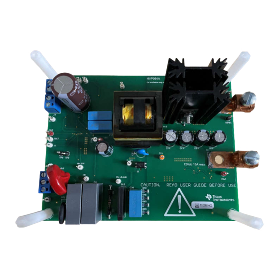
UCC25660EVM-064 180W LLC Resonant DC-DC Converter (Top View)
SLUUCV2 – OCTOBER 2023
Submit Document Feedback
– User option to disable
– Integrated PFC on/off control signal
•
Combined resonant current and resonant capacitor
voltage sensing through one pin
•
Adaptive dead-time
•
X-capacitor discharge
•
Automatic capacitive region avoidance
•
Adaptive soft start with minimized inrush current
•
Complete sets of protections:
– Cycle-by-cycle current limit, OCP1 protection
– Configurable over power protection
– OVP, internal & external OTP
– Vin & VCC UVLO
– Inbuilt 19.5 V VCC Clamp
•
Test points to facilitate device and topology
evaluation
Applications
•
SMPS power supply for TV
•
Industrial AC-DC adapters
•
Power tools
•
Medical power supply
•
Multifunctional printer
•
Enterprise and cinema projector
•
PC power supply
•
Gaming console power supply
•
Lighting
Copyright © 2023 Texas Instruments Incorporated
UCC25660x Half Bridge LLC Evaluation Module
Description
1
Advertisement
Table of Contents

Related Manuals for Texas Instruments UCC25660 Series


Summary of Contents for Texas Instruments UCC25660 Series
- Page 1 – Audible frequency range skip for reduced • Gaming console power supply audible noise • Lighting UCC25660EVM-064 180W LLC Resonant DC-DC Converter (Top View) SLUUCV2 – OCTOBER 2023 UCC25660x Half Bridge LLC Evaluation Module Submit Document Feedback Copyright © 2023 Texas Instruments Incorporated...
- Page 2 General Texas Instruments High Voltage Evaluation (TI HV EVM) User Safety Guidelines www.ti.com General Texas Instruments High Voltage Evaluation (TI HV EVM) User Safety Guidelines WARNING Always follow TI's set-up and application instructions, including use of all interface components within the recommended electrical rated voltage and power limits.
-
Page 3: Kit Contents
The UCC25660x provides several protection features ranging from cycle-by-cycle protection, capacitive region operation avoidance, external OVP and OTP to enhance the reliability of the LLC power stage. SLUUCV2 – OCTOBER 2023 UCC25660x Half Bridge LLC Evaluation Module Submit Document Feedback Copyright © 2023 Texas Instruments Incorporated... -
Page 4: Recommended Test Setup
High voltages that can cause injury exist on this evaluation module (EVM). Please make sure all safety procedures are followed when working on this EVM. Never leave a powered EVM unattended. UCC25660x Half Bridge LLC Evaluation Module SLUUCV2 – OCTOBER 2023 Submit Document Feedback Copyright © 2023 Texas Instruments Incorporated... -
Page 5: Test Points
Input voltage return terminal AC Input 3-pin, AC power input, 85–265 V VOUT Output voltage positive terminal SGND Output voltage ground terminal SLUUCV2 – OCTOBER 2023 UCC25660x Half Bridge LLC Evaluation Module Submit Document Feedback Copyright © 2023 Texas Instruments Incorporated... -
Page 6: Test Procedure
3. Shut down the electronic load. WARNING High voltage can still be present on the resonant capacitors after turning off the DC source. UCC25660x Half Bridge LLC Evaluation Module SLUUCV2 – OCTOBER 2023 Submit Document Feedback Copyright © 2023 Texas Instruments Incorporated... -
Page 7: Performance Data And Typical Characteristic Curves
Normal 92.32533 221.9 90.979 11.997 118.89 Normal 92.30592 159.05 65.2105 11.997 122.4 Normal 91.98672 120.38 49.3558 11.997 3.75 125.4 Normal 91.1519 SLUUCV2 – OCTOBER 2023 UCC25660x Half Bridge LLC Evaluation Module Submit Document Feedback Copyright © 2023 Texas Instruments Incorporated... - Page 8 Figure 3-1. No Load (0 A) Startup (Ch1 = ISNS; Ch2 = LO; Ch4 = V Figure 3-2. Full Load (15 A) Startup (Ch1 = ISNS; Ch2 = LO; Ch4 = V UCC25660x Half Bridge LLC Evaluation Module SLUUCV2 – OCTOBER 2023 Submit Document Feedback Copyright © 2023 Texas Instruments Incorporated...
- Page 9 DC input. Figure 3-4. Thermal Image Top Figure 3-5. Thermal Image Top Table 3-3. Component Temperature Component Temperature (°C) 77.3 SLUUCV2 – OCTOBER 2023 UCC25660x Half Bridge LLC Evaluation Module Submit Document Feedback Copyright © 2023 Texas Instruments Incorporated...
-
Page 10: Output Voltage Ripple
Figure 3-6. No Load (0 A) Output Ripple (Ch4 = V Figure 3-7. Full Load (15 A) Output Ripple (Ch4 = V UCC25660x Half Bridge LLC Evaluation Module SLUUCV2 – OCTOBER 2023 Submit Document Feedback Copyright © 2023 Texas Instruments Incorporated... - Page 11 Figure 3-9. Steady State Waveforms at 15 A Load (Ch1= ISNS; Ch2 = LO; Ch3 = SW; Ch4 = I_OPT) SLUUCV2 – OCTOBER 2023 UCC25660x Half Bridge LLC Evaluation Module Submit Document Feedback Copyright © 2023 Texas Instruments Incorporated...
- Page 12 Figure 3-10. Steady State Waveforms at 1 A Load (Ch1= ISNS; Ch2 = LO; Ch3 = SW; Ch4 = I_OPT) Figure 3-11. Steady State Waveforms at 0 A (Ch1= ISNS; Ch2 = LO; Ch3 = SW; Ch4 = I_OPT) UCC25660x Half Bridge LLC Evaluation Module SLUUCV2 – OCTOBER 2023 Submit Document Feedback Copyright © 2023 Texas Instruments Incorporated...
- Page 13 The following waveform shows the X-Capacitor discharge after the AC input of 265 VAC is disconnected. 390 VDC is applied to the DC input. Figure 3-12. X-Cap Discharge (Ch1 = Voltage across X-Cap, C40 and C41) SLUUCV2 – OCTOBER 2023 UCC25660x Half Bridge LLC Evaluation Module Submit Document Feedback Copyright © 2023 Texas Instruments Incorporated...
- Page 14 10.0k 10.0k 150pF PGND PGND 33.2k 0.01uF 80.6k 2N7002K-T1-E3 TLVH431ACDBZR Standby_Secondary 16.9k SGND SGND SGND Figure 4-1. UCC25660EVM-064 Power Stage Schematic UCC25660x Half Bridge LLC Evaluation Module SLUUCV2 – OCTOBER 2023 Submit Document Feedback Copyright © 2023 Texas Instruments Incorporated...
- Page 15 100pF 100pF 0.1uF SGND SGND SGND SGND SGND SGND Vout TPS71550DCKR 1µF 1µF SGND SGND SGND Figure 4-2. UCC25660EVM-064 Control Schematic SLUUCV2 – OCTOBER 2023 UCC25660x Half Bridge LLC Evaluation Module Submit Document Feedback Copyright © 2023 Texas Instruments Incorporated...
-
Page 16: Pcb Layouts
Hardware Design Files www.ti.com 4.2 PCB Layouts Figure 4-3. UCC25660EVM-064 (Top View) Figure 4-4. UCC25660EVM-064 (Bottom View) UCC25660x Half Bridge LLC Evaluation Module SLUUCV2 – OCTOBER 2023 Submit Document Feedback Copyright © 2023 Texas Instruments Incorporated... -
Page 17: Bill Of Materials
Mounting Kit For TO-220 Heat Sinks 4880SG Q1, Q3 Power Transistor MOSFET N-Channel Enhancement 600 V 21 A IPB60R105CFD7ATMA1 3-Pin D2PAK T/R SLUUCV2 – OCTOBER 2023 UCC25660x Half Bridge LLC Evaluation Module Submit Document Feedback Copyright © 2023 Texas Instruments Incorporated... - Page 18 750 kHz Wide VIN/VOUT Range LLC Controller Optimized for UCC256601DDBR Light Load Efficiency 5 Additional Information Trademarks All trademarks are the property of their respective owners. UCC25660x Half Bridge LLC Evaluation Module SLUUCV2 – OCTOBER 2023 Submit Document Feedback Copyright © 2023 Texas Instruments Incorporated...
- Page 19 STANDARD TERMS FOR EVALUATION MODULES Delivery: TI delivers TI evaluation boards, kits, or modules, including any accompanying demonstration software, components, and/or documentation which may be provided together or separately (collectively, an “EVM” or “EVMs”) to the User (“User”) in accordance with the terms set forth herein.
- Page 20 www.ti.com Regulatory Notices: 3.1 United States 3.1.1 Notice applicable to EVMs not FCC-Approved: FCC NOTICE: This kit is designed to allow product developers to evaluate electronic components, circuitry, or software associated with the kit to determine whether to incorporate such items in a finished product and software developers to write software applications for use with the end product.
- Page 21 www.ti.com Concernant les EVMs avec antennes détachables Conformément à la réglementation d'Industrie Canada, le présent émetteur radio peut fonctionner avec une antenne d'un type et d'un gain maximal (ou inférieur) approuvé pour l'émetteur par Industrie Canada. Dans le but de réduire les risques de brouillage radioélectrique à...
- Page 22 www.ti.com EVM Use Restrictions and Warnings: 4.1 EVMS ARE NOT FOR USE IN FUNCTIONAL SAFETY AND/OR SAFETY CRITICAL EVALUATIONS, INCLUDING BUT NOT LIMITED TO EVALUATIONS OF LIFE SUPPORT APPLICATIONS. 4.2 User must read and apply the user guide and other available documentation provided by TI regarding the EVM prior to handling or using the EVM, including without limitation any warning or restriction notices.
- Page 23 Notwithstanding the foregoing, any judgment may be enforced in any United States or foreign court, and TI may seek injunctive relief in any United States or foreign court. Mailing Address: Texas Instruments, Post Office Box 655303, Dallas, Texas 75265 Copyright © 2023, Texas Instruments Incorporated...
- Page 24 TI products. TI’s provision of these resources does not expand or otherwise alter TI’s applicable warranties or warranty disclaimers for TI products. TI objects to and rejects any additional or different terms you may have proposed. IMPORTANT NOTICE Mailing Address: Texas Instruments, Post Office Box 655303, Dallas, Texas 75265 Copyright © 2023, Texas Instruments Incorporated...
Need help?
Do you have a question about the UCC25660 Series and is the answer not in the manual?
Questions and answers