
Related Manuals for NSB FAN FD952 54


Summary of Contents for NSB FAN FD952 54
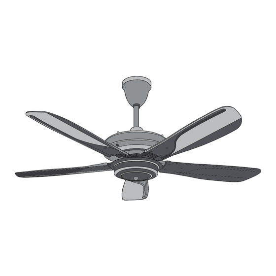
- Page 1 FD952 54 RF 8 SPEED + TURBO LAST MEMORY TIMER FAN MODES USER MANUAL & INSTALLATION GUIDE...
-
Page 2: Table Of Contents
Tables of Contents Safety Precaution …………………………………………………………………………………………….……………….………………..………………... Parts & Accessories ………………………………………………………………………………………….……………….………………..………………... Fan Installation Instruction……………………………………………………………………………….……………….………………..………………... Fan Mounting ……………………………………………………………………………….……………….………………..………………...……….……….. Blades Assembly……………………………………………………………………………….……………….………………..…………………………………. 5 Accessories Assembly ……………………………………………………………………………………………………………………………………… 5 Electrical Connection ……………………………………………………………………………………………………………………………………………… 6 Install Canopy ………………………………………………………………………………………………………………………………………………………… Using Your Ceiling Fan …………………………………………………………………………………………………………………………………………… 7 Maintenance ……………………………………………………………………………………………………. …………………………………………………… 8 Troubleshooting …………………………………………………………………………………………………………………………………………………. -
Page 3: Parts & Accessories
Parts & Accessories 01 Safety cable x1 02 Grounding wire x1 03 Lead wire x2 04 Canopy x1 05 Canopy screws x1 06 Down rod x1 07 Bolt x2 08 Stop pin x2 09 Nut x2 10 Spring washer x2 11 Flat washer x2 12 Yoke cover x1 13 Collar cover for screws x2... -
Page 4: Fan Installation Instruction
Fan Installation Instruction IMPORTANT: SWITCH OFF THE ELECTRICAL MAINS THE CIRCUIT BREAKER FUSE BOX. Follow the steps below to hang your fan properly. 1. Insert the downrod through the canopy and yoke cover 2. Through the lead wire and safety cable out the top of downrod. 3. -
Page 5: Fan Mounting
Fan Mounting 1. “J” Hook mounted ,When mounting the fan, ensure that the safety cable is loop across the “J” hook. 2. “U” Hook mounted Remove the bolt, stop pin, nut, washer and rubber pulley from the downrod. Place the rubber pulley onto “U” hook and fix back the bolt, stop pin, nut and washer. Stop 3. -
Page 6: Blades Assembly
Bolt WARNING:Safety Cable Safety Wire must be fixed correctly. May cause injury if ceiling fan drops. Blades Assembly 1.Tighten the blades with screws provided in the screw bag, each Blade uses 2 pieces of Screw. 2.Ensure the screw (10 PCS) for securing the blade are tightly screwed Accessories Assembly Connect the plug on motor to plug in switch housing .tight 3 screws beside of switch housing. -
Page 7: Electrical Connection
Electrical Connection Connect the red & black wire to the house’s supply wire. Diagram shows a complete assembly of the ceiling fan with safety wire mounted on the hook.Supply leads accommodated in the canopy. RED----------LIVE WIRE BLACK------NEUTRAL WIRE YELLOW GREEN -----GROUND WIRE... -
Page 8: Install Canopy
Install Canopy 1. Raise the Canopy and tighten it with the Set Screw. Using Your Ceiling Fan RF Transmitter Manual Installation 1. Install the remote holder on wall with the 2 screws provided 2. Install provided battery into the remote control. -
Page 9: Maintenance
NOTE 1. Remote pack includes 1.5V (AAA) battery x 2 pcs 2. For ceiling fan without light model, the light button has no function. Maintenance Due to fan’s natural movement, connections may get loose after a period of usage. To ensure a proper and safety usage, We are highly recommended to inspect and tighten all connections every 6 months. -
Page 10: Troubleshooting
Troubleshooting Check on the following before lodging a service report. SYMPTOM PROBLEM SOLUTION 1. Main cables not connected 1. Check main and branch circuit Fan not moving 2. Wire connection loose Breakers or fuse. 2. Check the line wires connections to the fan and switch housing.
Need help?
Do you have a question about the FD952 54 and is the answer not in the manual?
Questions and answers