Table of Contents
Advertisement
Quick Links
Advertisement
Table of Contents

Subscribe to Our Youtube Channel
Related Manuals for Major tech MT994


Summary of Contents for Major tech MT994
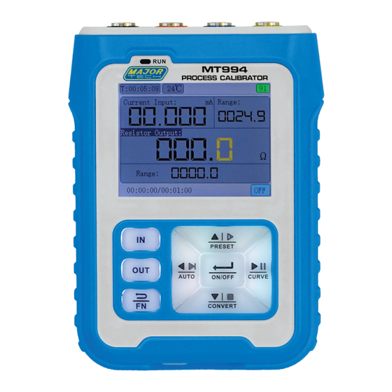
- Page 1 INSTRUCTION MANUAL MT994 MULTIFUNCTION PROCESS CALIBRATOR...
-
Page 3: Table Of Contents
Page no Contents 1. Safety Instructions.................4 2. Product Overview ................4 2.1. Function Introduction ..............4 2.2. Interface Terminal ..............5 2.3. Power & Charge ..............5 3. Button Panel Introduction ..............6 3.1. Button Function Operation Description ........6 4. Display and Signal Description ............7 4.1. -
Page 4: Safety Instructions
• When there is any quality problem with the instrument or when there is a question about using the instrument. You can contact Major Tech customer service and we will resolve it for you. -
Page 5: Interface Terminal
2.3. Interface Terminal There are 4 inner diameter 4mm wiring ports on the top surface, which are represented by different colour rings. The blue port (IN-) is an alternate function, and it is also an input-, which can be switched to a 24V independent test power supply. The (IN-) port is internally shorted with the black (COM) port in the input state. -
Page 6: Button Panel Introduction
3. BUTTON PANEL INTRODUCTION All buttons are made of white translucent silicone material. The colour LED backlight is set under the buttons, which can make the key surface change colour with the change of function and mode, providing a more intuitive status indication. -
Page 7: Display And Signal Description
4 - (FN) Exit Return key: In the main interface, click (FN), it will turn into a red light to activate the downshift function of other keys (enter different modes, etc.). In the setting interface, the function of (FN) is to return. 5 - (Main Interface): Main display interface. -
Page 8: Switching Of Signal Types
Output Circuit Voltage: The MT994 can set current output no-load voltage. The purpose of 12V is to save power. Some devices require a 24V drive capability. - Page 9 Output Peak Value: The level height of the output waveform, the highest is 24V. Input Counting Method: The rising edge means that the level rises from 0V to the peak value of the pulse, and the counter is incremented by 1. A falling edge indicates that the input level falls to the OV counter and increments by 1.
-
Page 10: Mv Millivolt Signal
4.6. mV Millivolt Signal Mode: The millivolt signal is divided into three modes: 110mV, thermocouple, WR thermocouple, in the main interface. When (FN) is white, press (IN/OUT) to switch. Type: Select the type of thermocouple TC-S, B, E, K, R, J, T, N. WR Type: Select the type of WR thermocouple WRE25, WRE26. -
Page 11: Ohm Resistance Signal
Activate Hold: After this item is checked, each time the machine is turned on, the 24V state will remain in the state of the last turn-on. Otherwise, every time you turn on the 24V, you need to turn it on manually. -
Page 12: Program Output
startup, the backlight of the up, down, left and right keys will turn off and have no function. 5.4. Program Output The programming output can automatically complete N cycles of signal output according to the parameters set by the user. This function is mainly used for the aging test of electric valve or pneumatic valve, or test work such as PLC program debugging. -
Page 13: History Record
3. Input automatic scaling: automatically adjust the scale range of the input signal, and automatically adjust the scale range of the y-axis according to the maximum and minimum values of the curve. 4. Acquisition time: the refresh interval of the curve, and the time scale will also change with it. -
Page 14: Fault Resolution & Equipment Maintenance
7 FAULT RESOLUTION & EQUIPMENT MAINTENANCE Fault Resolution No response when MT994 is turned on: 1. Determine if the battery has power and if the indicator light is normal when charging. 2.Firmware upgrade error operation leads to system crash. -
Page 15: Equipment Maintenance
Do not place this unit in places with high humidity, dust, direct sunlight, outdoors, or near high temperatures. 7.3. Firmware Upgrade MT994 uses USB emulated U disk for firmware upgrade. Upgrade Steps: 1. Plug the meter into the PC, and turn it on. Wait for the PC to recognize the USB drive named "Bootloader". -
Page 16: Specifications
8. SPECIFICATIONS Signal Range Precision Resolution Impedance ±(0.02%+0.003) 0.001mA 100Ω Current (mA) 0~24mA ±(0.02%+0.003) 0.001V 500K Voltage(V) 0~24V ±(0.02%+0.003) 0.001mA 100Ω Passive (XMT) 0~24mA ±(0.1%+0.005) 0.01mA 100Ω 24V loop 0~24mA ±2% 5 digits FRQ (Hz) 0~9999Hz ±(0.03%+0.03) 0.01mV -10~100mV ±(0.2%+1) 1°C TC (TC-S) 0~1760°C... - Page 20 MAJOR TECH (PTY) LTD South Africa Australia www.major-tech.com www.majortech.com.au sales@major-tech.com info@majortech.com.au...
Need help?
Do you have a question about the MT994 and is the answer not in the manual?
Questions and answers