Table of Contents
Advertisement
Quick Links
Advertisement
Table of Contents

Subscribe to Our Youtube Channel
Related Manuals for Major tech MT550


Summary of Contents for Major tech MT550
- Page 1 INSTRUCTION MANUAL MT550 DIGITAL INSULATION TESTER...
-
Page 3: Table Of Contents
Contents Page no 1. Safety Information................4 2. Safety Symbols..................4 3. Specifications..................4 3.1. General Information..............4 3.2. Electrical Specifications............5 4. Parts & Controls.................7 5. Battery Replacement.................7 5.1. How to connect test leads............7 5.2. Battery Check-UP & Replacement..........7 5.3. Test Lead Check...............7 6. Insulation Resistance Measurements...........8 6.1. -
Page 4: Safety Information
1. SAFETY INFORMATION • Read the following safety information carefully before attempting to operate or service the meter. • To avoid damages to the instrument do not apply the signals which exceed the maximum limits shown in the technical specifications tables. •... -
Page 5: Electrical Specifications
Range Function Display Large LCD with dual display Measurement Range 200Ω, 200kΩ, 200MΩ/250V, 200MΩ/500V, 2000MΩ/1000V, 750V/ACV, 1000V/DCV. Sampling Rate 2.5 times per second. Zero Adjustment Automatic adjustment. Over Range Indicator Number 1 of highest digit is displayed. Low Battery Indication The is displayed when the battery Voltage drops below the operating voltage. - Page 6 DC Voltage Range Resolution Accuracy Input Overload Impedance Protection 1000V 10MΩ 1000Vrms ±(0.8%+3) AC Voltage (40Hz~400Hz) Range Resolution Accuracy Input Overload Impedance Protection 750V ±(1.2%+10) 10MΩ 750Vrms Meg OHMS Range Resolution Accuracy Terminal Voltage 200MΩ/250V 0.1MΩ 250V +10%~-0% ±(3%+5) 200MΩ/500V 0.1MΩ...
-
Page 7: Parts & Controls
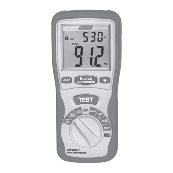
4. PARTS & CONTROLS 1. Digital Display 6. Rotary Function switch 2. Data Hold Button 7. VΩ Jack 3. Lock Button 8. COM input jack 4. Backlight Button 9. Pothook 5. Test Button 10. Battery Cover 5. BATTERY REPLACEMENT 5.1. How to connect test leads. a) On MΩ... -
Page 8: Insulation Resistance Measurements
6. INSULATION RESISTANCE MEASUREMENTS 6.1. Measurements at 200MΩ/250V This is the voltage used for the majority of insulation resistance tests on normal installation requirement. To measure insulation resistance, press the test button to power on the tester. The LCD will displayed the insulation resistance. -
Page 9: Low Resistance (Continuity) Measurements
7. LOW RESISTANCE (CONTINUITY) MEASUREMENTS 1. Set the range switch to 200Ω Position 2. Connect the red test lead to the V Ω terminal and black to the COM terminal. 3. Connect the tips of the test leads to both ends of the circuit under test read resistance in Ω... - Page 10 CABLES Disconnect the cable from the line. Also disconnect opposite end to avoid errors due to leakage from other equipment. Check each conductor to ground and /or lead sheath by connecting one megohmmeter lead to a ground and /or lead sheather and the other megohmmeter lead to each of the conductors in turn.
- Page 12 MAJOR TECH (PTY) LTD South Africa Australia www.major-tech.com www.majortech.com.au sales@major-tech.com info@majortech.com.au...
Need help?
Do you have a question about the MT550 and is the answer not in the manual?
Questions and answers