Table of Contents
Advertisement
Advertisement
Table of Contents

Subscribe to Our Youtube Channel
Related Manuals for Major tech MT390


Summary of Contents for Major tech MT390
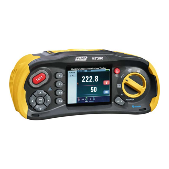
- Page 1 INSTRUCTION MANUAL MT390 MULTIFUNCTION INSTALLATION TESTER...
-
Page 3: Table Of Contents
Contents Page no 1. Safety....................4 1.1. Safety Considerations..............4 1.2. Safety Symbols................4 1.3. Terminology................4 1.4. Caution..................4 1.5. Warnings...................5 1.6. Declaration of Conformity............5 1.7. Error Codes................6 2. Specifications..................6 2.1. Specifications................6 2.2. Insulation..................8 2.3. General Specifications..............8 3. Instrument Overview................9 3.1. Front View.................9 3.2. Connector Panel...............10 3.3. -
Page 4: Safety
1. SAFETY WARNING: You must read and completely understand the Safety Considerations part of this manual before using the instrument. 1.1. SAFETY CONSIDERATIONS • This manual contains instructions regarding the safe use and the proper functioning of the instrument. • If not complied with, the user could be exposed to danger and the instrument to possible damage. -
Page 5: Warnings
1.5. WARNINGS • Make sure to read and fully understand the instruction contained within this manual prior to use. • This instrument is not intrinsically safe therefore do not use the instrument in hazardous environments. • In order to prevent fire and/or electrical shock, do not use the instrument in wet, damp or highly humid environments. -
Page 6: Error Codes
1.7. ERROR CODES • Various error conditions are detected by the tester and are indicated with the icon, "Err", and an error number on the primary display. • These error conditions disable testing and, if necessary, stop a running test. Error Condition Code Code Solution Solution Fault Voltage 1... - Page 7 Function Range Resolution Accuracy LINE Resistance 0.23 to 9.99Ω 0.01Ω ±(4% of reading + 6 L- N 10.0 to 99.9Ω 0.1Ω digits) 100 to 999Ω 1Ω Measuring Current: 8A to 25.0A. Range of the Voltage Used: 195VAC to 260VAC (50,60Hz). Function Range Resolution Accuracy...
-
Page 8: Insulation
2.2. INSULATION Terminal Range Resolution Test Current Short Voltage Circuit Current 125V 0.125~4.000MΩ ±(3%+10) 1mA at load 125kΩ ≤1mA (0%~ 4.001~40.00MΩ ±(2%+10) +10%) 40.01~400.0MΩ ±(4%+5) 400.1~1000MΩ ±(5%+5) 250V 0.250~4.000MΩ ±(3%+10) 1mA at load 250kΩ ≤1mA (0%~ 4.001~40.00MΩ ±(2%+10) +10%) 40.01~400.0MΩ ±(3%+2) 400.1~1000MΩ... -
Page 9: Instrument Overview
3. INSTRUMENT OVERVIEW 3.1. FRONT VIEW 1 - TEST Button • The TEST Button is surrounded by a "Touch Pad". • The touch pad measures the potential between the operator and the tester's PE terminal. • If you exceed a 100V threshold, the D symbol above the touch pad is illuminated. -
Page 10: Connector Panel
3.2. CONNECTOR PANEL 1 - lnput Terminal to Operate the Switched Probe 2 - Line Input 3 - Protective Earth Input 4 - Neutral Input 5 - lnput Terminal to Operate the Switched Probe 6 - TV OUT 7 - System Reset 8 - USB Connector 9 - Micro SD Card Slot 10 - Power Supply Socket... -
Page 11: Battery & Fuse
3.3. BATTERY & FUSE 1 - Battery Cover 2 - Fuse 5A/600V 3 - Fuse 5A/600V 4 - Fuse 500mA/600V 5 - Battery Cells (Size AA) -
Page 12: Understanding The Display
3.4. UNDERSTANDING THE DISPLAY Annunciator Annunciator Function Value Function Value AUTO Continuity 0.5Ω x1/2 1.0Ω 2.0Ω 5.0Ω 10.0Ω RAMP 20.0Ω Loop/PFC LL-PE 50.0Ω 50.0Ω Terminal Voltage 125V V/Phase L-PE 250V 500V 1000V 10 12... - Page 13 No. Annunciator Meaning No. Annunciator Low battery icon See Function Value Indicates the Trip Current 30mA batterystatus. 100mA 100% 300mA 500mA 650mA 1000mA Low Battery. 10mA for additional Current NO Trip information on Hi Amp batteries and power management. Beeper Beeper.
-
Page 14: How To Use The Tester
No. Annunciator Meaning Prospective Earth Fault Current. Calculated from voltage and loop impedance which is measured line to protective earth. Prospective Short Circuit. Calculated from measured voltage and impedance when reading line to neutral. Being tested High Voltage Warning Warning 4. - Page 15 4.1.2. Displayed Icons (Symbols) & Messages in LOOP/PFC Function Indicates the correct input terminal connectivity, the user should connect the test leads to the appropriate terminals. Indicates L connection is connected on the N input terminal and vice-versa. Indicates no connection on the PE input terminal. Notes: Indicates the Battery Status •...
- Page 16 Message: Half: Appears during the auto test when red has operated on the x ½ test. Half Trip: Appears during the manual test when red has operated on the x ½ test. UL OVER: Appears when UF voltage exceeds the previously set UL voltage. (UL voltage can be set to 25V or 50V) The user must check the impedance between L-PE.
-
Page 17: Using The Loop/Pfc Function
4.2. USING THE LOOP/PFC FUNCTION 1. Before you do a loop impedance test, use the zero adapter to zero the test leads or the mains cord. 2. Press and hold F4 Button for more than two seconds until the " "... - Page 18 4.2.2. LOOP/Pfc Function Menu Operation F1 Button: Pop-up and shut down Loop/PFC menu, shut down mode is activated when the user selects. F2 Button: Pop-up and shut down Current menu, shut down mode is activated when the user selects. F3 Button: None F4 Button: Press the F4 button 3s, triggering zero function.
- Page 19 4.2.3. Using the Hi Amp LOOP Measurement to be selected where the circuit is not protected by the inclusion of an RCD 1. Turn the rotary switch to the LOOP/PFC Position. 2. Press F2 Button to change from No Trip to Hi Amp. 3.
- Page 20 4.2.4. Using the L-N Line Impedance Measurement 1. Turn the rotary switch to the LOOP/PFC Position. 2. Press F1 Button to change from L-PE to L-N. 3. Connect the test leads. 4. lf voltage of the L-PE on the lower left appears, the unit is ready to test. 5.
-
Page 21: Using The Rcd Function
4.3. Using The RCD Function • You can select UL Voltage by pressing and hold F3 Button for more than two seconds (25V or 50V). • UF value appears is the contact voltage on the screen. Function Button Description Button AUTO RCD tΔ... - Page 22 • Using the Functions activated by F1 Button. 4.3.1. Using the AUTO Mode 1. Turn the rotary switch to the RCD Position. 2. lnitial screen is setup to the AUTO. 3. Using the F2 and F3 Button, select the rating and the type of the RCD. 4.
- Page 23 4.3.2. Using the x½, x1 and x5 Manual Selection 1. Turn the rotary switch to the RCD Position. 2. Press F1 and aspect Button from the AUTO to select x1/2, x1 and x5. 3. Using the F2 and F3 Button, select the RCD’s trip current and type of the RCD (General/Selective).
- Page 24 4.3.3. Using the RAMP Function 1. Turn the rotary switch to the RCD Position. 2. By pushing the F1 Button select RAMP from AUTO. 3. Using the F2 and F3 Button, select the RCD’s trip current and type of the RCD. 4.
-
Page 25: Using The Voltage Function
F1 Button: Pop-up and shut down RCD time/trip menu, shut down mode is activated when the user selects. F2 Button: Pop-up and shut down Trip Current menu, shut down mode is activated when the user selects. F3 Button: Pop-up and shut down Type of RCD menu, shut down mode is activated when the user selects. -
Page 26: Using The Phase Sequence Function
4.5. Using the Phase Sequence Function 1. Turn the rotary switch to the Voltage Position. 2. Press F1 Button to make symbol is displayed. 3. Connect the test leads L1, L2, L3. 4. When the instrument is energized the sequence will be displayed automatically. -
Page 27: Voltage/Phase Function Menu Operation
4.6. Voltage/Phase Function Menu Operation Fl Button: Pop-up and shut down Voltage/Phase menu, shut down mode is activated when the user selects. F2 Button: None F3 Button: None F4 Button: None Up Button: Up menu to select the current active sub-options. Down Button: Down menu to select the current active sub-options. -
Page 28: Using The Rf Function
F1 Button: Pop-up and shut down Insulation Voltage Selection menu, shut down mode is activated when the user selects. F2 Button: Pop-up and shut down Insulation Beeper menu, shut down mode is activated when the user selects. F3 Button: Pop-up and shut down Insulation Auto Lock menu, shut down mode is activated when the user selects. -
Page 29: Using The Low Ohm Function
• This test requires an accessory stake kit. Connect as shown in figure. • Best accuracy is achieved with the middle stake at 62% of the distance to the far stake. • The stakes should be in a straight line and wires separated to avoid mutual coupling. - Page 30 4.9.1. LOW OHM Function Menu Operation F1 Button: Pop-up and shut down LOW OHM Continuity menu, shut down mode is activated when the user selects. F2 Button: Pop-up and shut down LOW OHM Beeper menu, shut down mode is activated when the user selects. F3 Button: None F4 Button:...
-
Page 31: Menu
4. Press and hold TEST until the reading settles. 5. lf the continuity beeper is enabled, press the F1 Button to set high limit resistance value, the tester beeps continuously for measured values less than high limit resistance and there is no stable reading beep for measured values greater than high limit resistance. -
Page 32: Languages
6.1. Languages • Press the " " and " " Button to select the Language. • Then ESC Button to esc and save the select the Language. 6.2. Date/Time • Press the " " and " " Button to select the date or time, then press the "... -
Page 33: Memory
6.4. Memory • Press the " " and " " Button to select the Working Space or Format. • Then press the " " Button to enter, press the ESC Button to esc and save. 6.5. Auto Screen Off • Default 3 Minutes. •... -
Page 34: System Default Settings
6.7. System Default Settings • Then press the " " Button to enter • Press the " " and " " Button to select whether you want to Reset. 6.8. System Upgrade • Then press the " " Button to enter 7. -
Page 35: Bluetooth
7.1. Bluetooth • Press the "◄" and "►" Button to select the on or off bluetooth. • Then ESC Button to esc and save. Note: Bluetooth Connect: 1. Turn on the Bluetooth function on the instrument using Menu Button 2. Turn on the Bluetooth of the Smartphone, press the Meterbox Pro icon and enter into the home interface. -
Page 36: Datalog
7.3. Datalog • Press the " " and " " Button to select the items. • Press the "◄" and "►" Button to set. Items Menu On or off the Datalog /Set Datalog time (Unit: Second) 8. Data Record • Press the " " and " "... -
Page 37: Data Record Preview
8.2. Data Record Preview • Press the " " and " " Button to select the items. • Press the "◄" and "►" Button to set. • Then press the " " Button to enter. • Press the ESC Button to esc data record preview. F1 Button: None F2 Button:... -
Page 38: Drawing
8.4. Drawing No. Annunciator Meaning File Name File Named: Primary display & measurement units. Primary display & measurement units. Coordinate Function Function Hours/Minutes/Seconds Record time L-FE Value L-N Value FE-N Value Arrows above or below the terminal indicator symbol indicate reversed polarity. - Page 39 MAJOR TECH (PTY) LTD South Africa Australia www.major-tech.com www.majortech.com.au sales@major-tech.com info@majortech.com.au...
Need help?
Do you have a question about the MT390 and is the answer not in the manual?
Questions and answers