Table of Contents
Advertisement
Quick Links
Advertisement
Table of Contents

Related Manuals for Major tech MT777


Summary of Contents for Major tech MT777
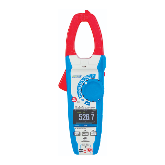
- Page 1 INSTRUCTION MANUAL MT777 AC/DC TRMS CLAMP METER with Datalogger & Mobile APP...
-
Page 3: Table Of Contents
Contents Page no 1. Introduction ................4 2. Safety ..................5 3. Description ................6 3.1. Meter Description .............. 6 3.2. Symbols Used on LCD Display ...........7 3.3. Key Description ..............7 4. Specifications ................ 8 4.1. AC/DC Current Measurements ......... 8 4.2. -
Page 4: Introduction
1. Introduction • Professional True RMS Industrial Digital Clamp meter and TFT color LCD display, providing fast A/D converting sampling time with high accuracy. • It is easy to find and solve the problems of the production equipments with Bluetooth technology. •... -
Page 5: Safety
2. Safety 2.1. lnternational Safety Symbols This symbol, adjacent to another symbol or terminal, indicates the user must refer to the manual for further information. This symbol, adjacent to a terminal, indicates that, under normal use, hazardous voltages may be present. Double insulation. -
Page 6: Description
3. Description 3.1. Meter Description 8-MENU Button 1-Current Clamp 9-Rotary Function Swith 2-Non-Contact AC Voltage Indicator Light 10-Data Hold/Flashlight Button 3-Clamp Trigger 11-Battery Cover 4-Relative/INRUSH/ESC Button 12-COM Input Jack 5-LCD Display 13-VΩHz% CAP TEMP Jack 6-MODE/VFD Button 14-Flashlight 7-RANGE Button 1000A 600A Temp... -
Page 7: Symbols Used On Lcd Display
3.2. Symbols Used on LCD Display Power Off Function Key Beeper Function Bluetooth Function Automatic/Manual Mode System’s Time Battery Capacity Measuring Unit Measuring Result Analogue Bar Graph 10. Function Keys 3.3. Key Description 1. MODE: Press the Mode key to switch the functions, and press for 2 seconds to switch to VFD AC Voltage when AC Voltage measurement. -
Page 8: Specifications
4. Operation NOTES: Read and understand all Warning and Caution statements in this operation manual prior to using this meter. NOTES: Set the function select switch to the OFF position when the meter is not in use. 4.1. AC/DC Current Measurements WARNING: Ensure that the test leads are disconnected from the meter before making current clamp measurements. -
Page 9: Inrush Current Measurements
4.2. Inrush Current Measurements 1. Set the function switch to the 600A or 1000A position. 2. Press the INRUSH button (Enter key for 2 seconds) to indicate “Inrush” on the display. Then measurement display “----” . 3. Clamp the cable to be motor. 4. -
Page 10: Ac+Dc Voltage Measurements
4.4. AC+DC Voltage Measurements CAUTION: Do not measure DC voltages if a motor on the circuit is being switched ON or OFF. Large voltage surges may occur that can damage the meter. 1. Set the function switch to the V AC/DC position. 2. -
Page 11: Loz Ac Voltage Measurements
4.7. LoZ AC Voltage Measurements WARNING: Risk of Electrocution. The probe tips may not be long enough to contact the live parts inside some 240V outlets for appliances because the contacts are recessed deep in the outlets. As a result, the reading may show 0 volts when the outlet actually has voltage on it. -
Page 12: Continuity Check
4.9. Continuity Check WARNING: To avoid electric shock, disconnect power to the unit under test and discharge all capacitors before taking any resistance measurements. Remove the batteries and unplug the line cords. 1. Set the function switch to the 1000A Ω... -
Page 13: Capacitance Measurements
4.11. Capacitance Measurements WARNING: To avoid electric shock, disconnect power to the unit under test and discharge all capacitors before taking any capacitance measurements. Remove the batteries and unplug 1000A the line cords. 600A Temp °C °F 1. Set the rotary function switch Ω... -
Page 14: Flexible Coil Current Measurements
4.13. Fexible Coil Current Measurements (use the MT740) 1. Set the function switch to the Flexible coil position. 2. Insert the black test lead banana plug into the 1000A 600A Temp negative COM jack. °C °F Ω Insert the red test lead INRUSH banana plug into the Bluetooth... -
Page 15: Hold Mode
4.15. Hold Mode • To freeze the display for any function, press key HOLD. And again press key HOLD to release freeze. • Press soft key SAVE will store the measurement to memory. 4.16. Capturing Minimum and Maximum Values • The MAX MIN Record mode captures minimum, and maximum input values. -
Page 16: Non-Contact Ac Voltage Measurement
4.19. Non-Contact AC Voltage Measurement WARNING: Risk of Electrocution. Before use, always test the voltage detector on a known live circuit to verify proper operation. 1. Touch the probe tip to the live conductor or insert into the live side of the electrical outlet. -
Page 17: Menu Operation
5. Menu Operation • Press Menu button to open the Menus, As show below • Press soft key Up / Down to select menu item or change the value of current focus item. • Press soft key Enter to enter the submenu or set focus on the current selected item. -
Page 18: Measurement Details
5.3. Measurement Details • Press soft key Up/Down to select Measurement item at Measurement menu, and Press soft key Enter to enter the menu. • This recalls all the measurements saved when the hold button was used and the readings were saved, refer to 4.15 (Hold Mode) •... - Page 19 3. In Record Menu. Press soft key Up/Down to select Start recording Item, and press soft key Enter to start one new recording. 4. In Record Menu. Press soft key Up/Down to select Recall recordings Item, and press soft key Enter to enter recall recording in memory. Then Press soft key Prev/Next view last or next recording.
-
Page 20: Meter Info Details
5.5. Meter Info Details • Press soft key Up/Down to select Meter Info item at main menu, and Press soft key Enter to enter Meter info interface. • This menu contains software’s version, hardware’s version and Free Memory. 5.6. Factory Set Details •... -
Page 21: Specifications
7. Specifications 7.1. Specifications Accuracy calculated as [%reading + (num. digits*resolution)] at 18 to 28°C; <75%HR. Function Range Resolution Accuracy 600.0mV 0.1mV ±(0.5% + 8 digits) DC Voltage 6.000V 0.001V 60.00V 0.01V ±(1.5% + 5 digits) 600.0V 0.1V 1000V Input impedance>10MΩ; Protection against overcharge: 1000VDC/AC RMS. AC TRMS Voltage 6.000V 0.001V... - Page 22 Function Range Resolution Accuracy Resistance and 600.0 Ω 0.1 Ω ±(1.0% + 10 digits) Continuity Test 6.000k Ω 0.001k Ω 60.00k Ω 0.01k Ω ±(1.5% + 5 digits) 600.0k Ω 0.1k Ω 6.000M Ω 0.001M Ω ±(2.5% + 5 digits) 60.00M Ω...
-
Page 23: General Specifications
7.2.General Specifications Clamp Jaw Opening 33mm approx. Display 3-5/6 digits (6000 counts) TFT Color LCD Continuity Check Threshold 50Ω; Test current < 0.5mA. Diode Test Test current of 0.3mA typical; Open circuit voltage < 3.3VDC typical. Over-Range Indication “OL” display Measurement Rate 3 readings per second, nominal Peak... - Page 24 MAJOR TECH (PTY) LTD South Africa Australia www.major-tech.com www.majortech.com.au sales@major-tech.com info@majortech.com.au...
Need help?
Do you have a question about the MT777 and is the answer not in the manual?
Questions and answers