Table of Contents
Advertisement
Quick Links
Advertisement
Table of Contents

Related Manuals for Major tech MT585


Summary of Contents for Major tech MT585
- Page 1 INSTRUCTION MANUAL MT585 15kV HIGH VOLTAGE INSULATION TESTER...
-
Page 3: Table Of Contents
Contents Page no 1. Safety Precautions..............4 2. Overview.................5 3. Features.................5 4. Specifications.................6 5. Connections................7 6. Instrument layout..............8 7. Measuring procedure..............9 8. Charge.................16 9. Maintenance & repair............16 10. Interface Connection and Operation........17... -
Page 4: Safety Precautions
1. Safety Precautions Electricity can cause severe injuries even with low voltages or currents. Therefore, it is extremely important that you read the following information before using your high voltage insulation tester. 1.1. This Instrument must only be used and operated by a competent trained person and in strict accordance with the instructions. -
Page 5: Overview
2. Overview This is a variable high voltage insulation tester from 500V to 15kV in 500V steps. The is menu driven and uses Dynamic Current Auto ranging technology. When pressing the on/off button, the top line of the display shows current year, month, date, hour and minutes indication. -
Page 6: Specifications
4. Specifications Function Range Test Voltage From 500V DC to 15kV DC Adjustable in 500V steps Preset buttons 1kV, 5kV, 10kV, 15kV Measuring ranges 1TΩ / 0.5kV 1TΩ at 0.5kV~30TΩ at 15kV Accuracy 1kV : 0~200GΩ 5kV : 0~1TΩ ±(5%rdg+5dgt) 10kV : 0~2TΩ... -
Page 7: Connections
5. Connections FIRST MEASUREMENT Measure without the guard to take everything into account and find out it if needs cleaning. DIRTY ELECTRICAL INSULATOR EQUIVALENT CIRCUIT DIRTY INSULATOR SECOND MEASUREMENT Measure with the guard to ensure insulator is correct. TYPICAL TEST Resistance due to contamination can be very low and lower the total resistance. -
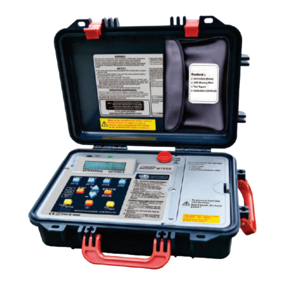
Page 8: Instrument Layout
10 - ESC button 11 - BACKLIT button 12 - Connection socket for data transmission 13 - Battery-charge socket 14 - Charge indicator -HV terminal GUARD terminal L.C.D. +HV terminal ⑭ MT585 ⑬ ⑫ ⑤ ② ③ ④ ⑥ ⑩ ⑧ ⑦... -
Page 9: Measuring Procedure
7. Measuring procedure This insulation tester provides one main function and four minor functions: Main Function: Insulation resistance test. Minor functions: Function 1 ─ Voltage meter Function 2 ─ RTC Adjustment Function 3 ─ Test Timer Function 4 ─ LOG Display Function 5 ─... - Page 10 2. TPress ① (ON/OFF) button. (Main page) 3. Select test voltage: 3.1. Select one from 1kV, 5kV, 10kV or 15kV, press (② , ③, ④ or ⑤) respectiv e l y . 3.2. To select voltage other than the four indicated, press anyone among ②, ③, ④, ⑤, then, press ⑥...
- Page 11 6. Read the test value on LCD display. 7. Press ⑧ (TEST/ STOP); LCD shows the "discharging". 8. To store the data, press ⑨ (ENTER/SAVE); LCD displays the picture shown in below. Note: When doing an insulation test, always connect the test leads to the object we want to measure before pressing the TEST button.
- Page 12 7.1.4. Date/time adjustment (RTC Adjustment) ─ Function 2 1. Press ① (ON/OFF) button. (Main page) 2. Press ⑥ (value-add) "+" 2 times; LCD display the following pictures respectively: 3. Press ⑨ (ENTER/SAVE) button. 4. Press ⑥ (value-add) "+" or ⑦ (value-reduce) "-" till the correct voltage is reached.
- Page 13 3. Press ⑨ (ENTER/SAVE), LCD displays the picture shown in below: 4. Press ⑥ value-add “+" or ⑦ value-reduce "-" to set the test time. 5. After setting is complete, press ⑨ (ENTER/SAVE) to confirm & save the data measured. 6.
- Page 14 5. Press ⑨ (ENTER/SAVE), LCD displays the "Volt" picture shown below: 6. Press ⑨ (ENTER/SAVE), LCD displays the "Date" and "Time" picture shown below: 7. Press ⑥ value-add "+" or ⑦ value-add"-" to find LOGS which has been saved. 8. Press ⑥ value-add “+" or ⑦ value-reduce "-" to select the required data value.
- Page 15 3. Press ⑨ (ENTER/SAVE) to inquire whether to clear up the data or not; LCD displays the picture shown below: Erase ─ press ⑨ (ENTER/SAVE). LCD displays the picture shown below: Not erase ─ press ⑩ (ESC) to go back to the main page. 7.1.8.
-
Page 16: Charge
8. Charge 8.1. Timing: After "Low Battery" is displayed on LCD display, perform battery charge; LCD displays the picture shown below: 8.2. Process: 1. Plug one end of charger into the battery plug-in socket (Fig ⑬); and the other end into the ACV power socket. 2. -
Page 17: Interface Connection And Operation
10. Interface connection and operation 10.1. Insulation Tester Installation Steps with the USB Flash Drive: 1. This program will install Insulation Tester on your computer automatically. 2. Click the "Next" key to set. 3. If you want to install a different folder, click Browse, and select another folder. - Page 18 4. Click the "Next" key. 5. It will show the information of all files are Installing to your personal computer.
- Page 19 6. It will show the information of Insulation tester has been successfully installed and then click "Finish" key. (Note: If your personal computer system is Windows 7, it will indicate the driver automatically. It's necessary to install the driver if your computer system is not windows 7, then the driver is in the compact disk (CD).
- Page 20 3. ② Right-click on Computer, ③ Click on Properties in the sub-menu. 4. The windows appears Control Panel Home, On the left hand side of the window ④ click on Device Manger.
- Page 21 5. The windows appears Device Manager. (Alternatively, you can: open the Run command window (Start Menu → Run… or press + R) and type "devmgmt.msc" without the quotation marks.) ⑤ Click on the arrow to the left of Ports "(COM & LPT)" to expand the listing.
- Page 22 7. In the window that appears ⑦ click on the Port Settings tab at the top and the display will change. ⑧ Click on the Advance button, the windows appears shows the Advance Setting for COMxx. 8. ⑨ Click on the COM Port number list to expand it and click on a COM port number within the range of COM1 to COM8 (preferably one not in use, avoid choosing COM1;...
- Page 23 9. Once the new COM port is chosen, ⑩ click on OK and again in the USB Serial Port Properties window. Close the device manager. 10.3. Insulation Tester Software Comm Port setting: 1. Connect data transmission cable to the InsulationTester. 2.
- Page 24 10.4. Insulation Tester Interface: ① RS 232 Connection. ② Main operation interface. ③ Memory saving and downloading interface. ④ Click the "Download Log from Device" key to download the current data and statistics.
- Page 25 ⑤ Click the "Chart Display" key to see the chart, picture shown in below:...
- Page 26 ⑥ Click the "Save Log" key to the file, picture shown in below:...
- Page 28 MAJOR TECH (PTY) LTD South Africa Australia www.major-tech.com www.majortech.com.au sales@major-tech.com info@majortech.com.au...
Need help?
Do you have a question about the MT585 and is the answer not in the manual?
Questions and answers