Advertisement
Quick Links
Advertisement

Related Manuals for Major tech MT195


Summary of Contents for Major tech MT195
- Page 1 INSTRUCTION MANUAL MT195 CABLE LOCATOR...
- Page 3 Contents Page no...
- Page 4 Contents Page no...
- Page 5 Open-Case Inspection When receiving this Cable Locator, please inspect it carefully to ensure no damage has occurred during transport. Generally accessories, control switches and connectors need to be checked. If there is any obvious damage or functional failure, please contact your supplier. Main parts: 1 - CD Bag 2 - Receiver: 1 pcs...
- Page 6 Safety Information This Cable Locator is produced in accordance with the safety specifications for electronic meters and testing instruments and has been completely tested before packing and transport. Before using this device, please read this Manual carefully and follow all of the instructions. Failure to adhere to these instructions or ignoring the warnings and cautions herein may lead to injury, threat to life or damage of equipment.
- Page 7 Attention! Please observe the following instructions to ensure safe operation and optimal performance. 1. Preliminary Inspection Before the first use, please check whether the cable locator can function normally and ensure it is not damaged during storage and transport. If there is any damage, please contact the supplier.
- Page 8 3. Use The following instructions should be followed to avoid electric shock, short circuit or explosion: 1. This cable locator can be directly used for live parts, but do take insulation measures in accordance with industrial safety codes to avoid electric shock and hurt.
- Page 9 6. The instrument may only be used under those conditions and for those purposes for which it was conceived. When modifying or changing the instrument, the operational safety is no longer ensured. 1. The working temperature of this Cable Locator is 0-40°C (32- 104°F).
- Page 10 1. OVERVIEW 1.1. Product Introduction When you are making a hole in the wall for installation of an air conditioner or on the floor for installation of a machine, or excavating a road, you have to know the layout of the cables, water pipelines or gas pipelines in the wall or ground to keep away from these facilities and avoid unnecessary troubles and even dangers.
- Page 11 1.2. Characteristics of This Cable Locator Ÿ Detecting cables, electrical lines, water/gas supply pipelines in walls or underground; Ÿ Detecting interruptions and short circuit in cables and electrical lines in walls or underground; Ÿ Detecting fuses and assigning current circuits; Ÿ...
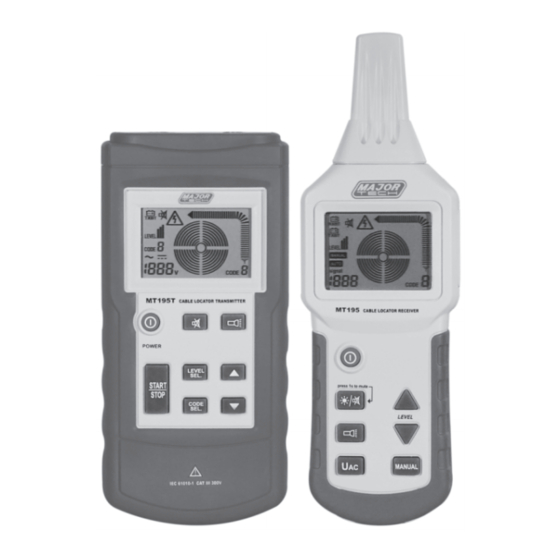
- Page 12 1.3. Names And Functions Of Parts 1.3.1. Sketch of transmitter 1 - LCD screen. 2 - Power on/off key. 3 - Key for setting/confirming transmitting power level (Level I, II or lll) 4 - Key for transmitting or stopping to transmit code information.
- Page 13 1.3.3. Sketch of receiver 1 - Flashlight. 2 - Probe head 3 - LCD screen 4 - Power on-off key 5 - Composite key for backlight and mute mode. Press briefly to enable/disable backlight and press for 1 second to enable/disable mute mode (under mute mode, both the keypad tone and...
- Page 14 1.3.4. Receiver display 1 - Symbol to indicate voltage/energy of the receiver's battery. 2 - Symbol to indicate voltage/energy of the transmitter's battery. 3 - Transmitting power level received (Level I, II or 111) 4 - Symbol of manual mode. 5 - Symbol of automatic mode.
- Page 15 2. Measuring Method 2.1. Measurement Precautions 1. As the connection of the transmitter with the mains supply may generate circuit current of milliamperes, in a live condition the earthing of the transmitter can be only connected with a neutral conductor. If transmitter connection is connected from the phase towards the protective conductor, the functional safety of the protective conductor must be tested first, in compliance with DIN...
- Page 16 For any application, the connections of the transmitter should ensure a closed circuit. £ll 2.This Cable Locator can only detect or locate lines correctly connected in accordance CAUTIONS to the physical principle described. Alternate connections of this Cable Locator 1. One-pole application: Connect the transmitter to only one conductor.
- Page 17 connect the other two terminals in the mains with each other. Under such circumstance, the modulated current will directly return to the transmitter through the mains. Optionally, the two test leads of the transmitter can be respectively connected to the two ends of the conductor. Besides, the "+"...
- Page 18 When the probe of the receiver passes the interruption position, the signal intensity as displayed by will have an obvious drop till it completely disappears. At this moment, press MANUAL button the receiver to switch it to manual mode and then use button to reduce the sensitivity as much as possible while ensuring that he receiver's screen can display the code transmitted by the...
- Page 19 3.1.2. Locating and tracing of lines and sockets Preconditions: Ÿ The circuit must be dead or disconnected. Ÿ Neutral line and protective earth wire must be connected and fully operational. Ÿ Connect transmitter to phase line and protective earth wire according to Fig.
- Page 20 3.1.3. Locating of line interruptions Preconditions: Ÿ The circuit must be dead or disconnected. Ÿ All lines which are not required must be connected to the auxiliary earth in accordance with Fig. 3-1-3. Ÿ Connect the transmitter to one lead and to an auxiliary earth according to Fig.
- Page 21 3.1.4. Locating of line interruptions using two transmitters When locating a line interruption using one transmitter to feed from one conductor end, the location of the interruptions may not be precisely located in case of bad conditions due to a field disturbance.
- Page 22 1. Proper or good earth should be ensured. 2. The transition resistance of a line interruption must be higher than 1 00kOhm. 3. The earth connected to the transmitter can be an auxiliary earth, earth from an earthed socket or a water pipe which is properly earthed.
- Page 23 1. During tracing along the line, the position at which the signal received by the receiver has an abrupt decline is the position of the interruption. 2. Adjust the transmitting power level of the transmitter to adapt it to different detection radiuses.
- Page 24 3.1.6. Detect the narrow (blocked) part of the laid non- metallic conduct Preconditions: Ÿ The conduit must be made of non-conductive materials (such as plastic); Ÿ The conduit must not be charged; Ÿ The transmitter is connected to a metal helical tube (metal tube or flexible conduit) and an auxiliary earth wire, as shown in Fig.3- 1-6;...
- Page 25 3.1.7. Detect the laid metal water pipe and metal heating pipe Preconditions: Ÿ The pipe must be made of metal materials (such as galvanized steel pipe); Ÿ The pipe to be detected should not be earthed. There should be a relatively high resistance between the pipe and the soil (otherwise the distance of detection will be very short);...
- Page 26 3.1.8 Detect the power supply circuit on the same floor When detecting the power supply circuit on the same floor, please take the following steps: 1. Tum off the main switch in the distribution box of this floor; 2. Disconnect the neutral wire in the distribution box of this floor from the neutral wires of other floors;...
- Page 27 3.1.9. Trace an underground circuit Preconditions: Ÿ The circuit must not be charged; Ÿ Connect the transmitter in a way shown in Fig.3-1-9; Ÿ The earth probe of the transmitter must be properly earthed; Ÿ Select the automatic mode of the receiver; Ÿ...
- Page 28 3.2. Dual-pole Applications 3.2.1 Applications in closed circuits It can be applied to charged circuits and uncharged circuits: In uncharged circuits, the transmitter only sends encoding signals to the circuit to be detected. In charged circuits, the transmitter not only sends encoding signals to the circuit to be detected, but also measures and displays the voltage of the charged circuit.
- Page 29 3.2.2 Search for the Circuit Breakers In a building with multiple residences, use the Land N ports on the socket of any residence to feed the signals from the transmitter (as shown in Fig.3-2-2), and adjust the transmitting power of the transmitter to a suitable level.
- Page 30 3.2.3 Search for short circuit in the circuit Preconditions: Ÿ The circuit must be discharged and disconnected; Ÿ Connect the transmitter according to Fig.3-2-3; Ÿ The measuring method is the same as that shown in the example. 1. lf there is current in the cable, disconnect the power first and make sure it's discharged.
- Page 31 3.2.4 Detect circuits laid relatively deep In dual-pole applications, if the loop line is made of core wires in cables with multiple core wires (such as NYM 3x1 .5mm2), the depth of detection will be greatly limited. The reason is that the short distance between the feeding line and the loop line causes a seriously distorted magnetic field.
- Page 32 3.2.5. Classify or determine the laid circuit Preconditions: Ÿ The circuit must be uncharged; Ÿ The ends of core wires must be twisted together and conduct with each other; Ÿ Connect the transmitter in a way shown in Fig.3-2-5; Ÿ The measuring method is the same as that in the example. 1.
- Page 33 3.3. Method to increase the effective radius of detecting charged circuits When the transmitter is directly connected to the phase line and neutral line, the signals are conducted on two parallel circuits (as shown in Fig.3-3-1), so the twisting of circuits may sometimes cause signals to counteract each other, leading to an effective radius of 0.5m at most.
- Page 34 3.4. Identify voltage in the grid and search for breakages in the circuit Preconditions: Ÿ The circuit must be charged with AC voltage; Ÿ The measurement must be conducted according to Fig.3-4; Ÿ Set the transmitter to "Grid Voltage Identification" mode (namely the UAC mode).
- Page 35 4. Other Functions 4.1. Voltmeter function of the transmitter If the transmitter is connected to a charged circuit and the external voltage is higher than 12V, the lower left part of the monitor of transmitter shows current value of voltage, and standard symbols are used to distinguish AC and DC circuits (see in the interface displayed on the transmitter), and the upper part of the monitor shows a lightning symbol with a...
- Page 36 5. Technical Parameters 5.1. Technical parameters of transmitter 5.1. Technical parameters of receiver...
- Page 37 6. Repair and Maintenance 1. If the detector is suspected of malfunctioning, please confirm that the electrical amperage of the battery is sufficient and the test lead is not broken. 2. Before sending back the detector for repair, please check the battery. Properly pack the apparatus to avoid damaging it during transportation.
- Page 38 Specific methods and steps to check the fuse of the transmitter: 1. Break all the measuring circuits of the transmitter; 2. Turn on the transmitter and put it in the transmitting status; 3. Set the transmitting power of transmitter to level I 4.
- Page 39 1. Before replacing the battery, the equipment must be turned off, all the connected measuring circuits must be cut off, and all the conducting wires for measurement must be removed. 2. Only the battery specified in the technical parameters table can be used. 3.
- Page 40 MAJOR TECH (PTY) LTD South Africa Australia www.major-tech.com www.majortech.com.au sales@major-tech.com info@majortech.com.au...
Need help?
Do you have a question about the MT195 and is the answer not in the manual?
Questions and answers