Table of Contents
Advertisement
Quick Links
Advertisement
Table of Contents

Related Manuals for Major tech MT700


Summary of Contents for Major tech MT700
- Page 1 INSTRUCTION MANUAL MT700 VOLTAGE & CURRENT TESTER...
-
Page 3: Table Of Contents
Contents Page no Safety..................4 1.1. lnternational Safety Symbols..........4 1.2. Safety Notes..............4 1.3. WARNINGS..............4 1.4. Safety Precautions before use.......... 5 1.5. Safety Advices..............5 Appropriate Usage..............6 Meter Description..............7 3.1. Meter Description............. 7 3.2. Symbols Used on LCD Display.......... 8 Operation................. -
Page 4: Safety
1. Safety 1.1. lnternational Safety Symbols WARNING of a potential danger, comply with instruction manual. CAUTION dangerous voltage, Danger of electrical shock. Double insulation. Important information. Consult the instruction sheet. Hazardous Voltage. Suitable for live working. This product complies with the WEEE Directive (2012/19/EU). Conforms to European Union Directives. -
Page 5: Safety Precautions Before Use
This instrument may only be used within the ranges specified and within low voltage systems up to 1000V. Prior to usage ensure perfect instrument function (e.g. on known voltage source). The voltage detector is not to be used, if the battery cover is open. The voltage detectors have to be kept dry and clean. -
Page 6: Appropriate Usage
• When the indication"Voltage Present" appears on a part that is expected to be disconnected from the installation, it is highly recommended confirming by another means (e.g. use of an adequate voltage detector, visual check of the disconnecting point of the electric circuit, etc.) that there is no operating voltage on the part to be tested and to conclude that the voltage indicated by the voltage detector is an interference voltage. -
Page 7: Meter Description
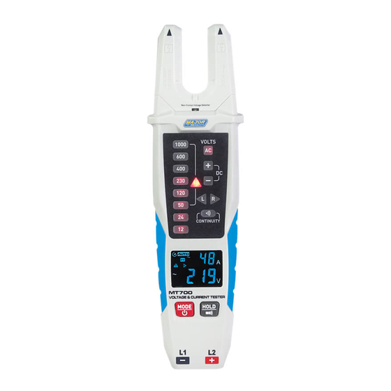
3. Description 3.1. Meter Description 1 - NCV 11 - LED for Left Rotary Field 2 - Current Jaws 12 - LCD Display 3 - NCV LED 13 - Power and Mode Button 4 - LEDs for Voltage Display 14 - Flashlight and Hold Button 5 - LED for AC Voltage 15 - Flashlight 6 - LED for Positive Voltage... -
Page 8: Symbols Used On Lcd Display
3.2. Symbols Used on LCD Display 1 - Auto Power Off 12 - Volts 2 - Auto Range Mode 13 - Number Display 3 - Alternating Current 14 - Direct Voltage 4 - Minus Sign 15 - Minus Sign 5 - Direct Current 16 - Alternating Voltage 6 - Number Display 17 - Right Rotary Field... -
Page 9: Operation
4. Operation 4.1. Preparing the Test Prior to every test. please ensure that the instrument is in perfect condition: • For example, keep an eye out for a broken housing, leaking batteries and damaged test leads. • Always carry out a function test before using the voltage tester, see below. -
Page 10: Voltage Test
4.4. Voltage Test • Connect both test probes with power source. • The voltage is displayed via LEDs, the measured voltage value will light up, the different indicating signals of the voltage detector (including the ELV limit indication) are not to be used for measuring purposes, the voltage is also shown on the LCD display. -
Page 11: Voltage And Current Measured Simultaneously
4.5. Voltage and Current Measured Simultaneously • To simultaneously measure voltage and current, insert the test leads into the meter and switch the meter on. • Connect the test leads to the power source. On the voltage display, the LCDs and LEDs will display the voltage measured. •... -
Page 12: Rotary Field Lndication
4.6. Rotary Field Indication • The voltage testers are equipped with a double-pole rotary field indicator. • The rotary phase indication is always active. the symbols "R" or "L" are always displayed, however the rotary direction can only be determined within a thee-phase system, here the instrument indicates the voltage between two external conductors. -
Page 13: Ncv Test
4.9. NCV Test • NCV cannot measure voltage, it can only sense whether there is voltage. • NCV induced voltage is not less than 100V. • Can only sense AC voltage. 5. Cleaning • Prior to cleaning, completely disconnect Voltage Tester from the measurement circuit. -
Page 14: Specifications
7. Specifications 7.1.General Specifications Voltage Detection Automatic Polarity Detection Full Range Range Detection Automatic Measurement Principle Double-pole and contact electrode Safety Standards EN61243-3:2014 Over Voltage Protection 1000V AC/DC Measurement Category CAT III 1000V / CAT IV 600V Power Supply 2 x 1.5V "AA" Batteries Power Consumption Max. - Page 16 MAJOR TECH (PTY) LTD South Africa Australia www.major-tech.com www.majortech.com.au sales@major-tech.com info@majortech.com.au...
Need help?
Do you have a question about the MT700 and is the answer not in the manual?
Questions and answers