Table of Contents
Advertisement
Quick Links
Advertisement
Table of Contents

Related Manuals for Major tech MT355


Summary of Contents for Major tech MT355
- Page 1 INSTRUCTION MANUAL MT355 LOOP IMPEDANCE PSC/PFC TESTER...
-
Page 3: Table Of Contents
Contents Page no 1. Safety ..................... 4 1.1. Safety Information..............4 1.2. Safety Symbols.................4 2. Description..................5 2.1. Meter Overview................5 2.2. Meter Description..............6 2.3. Display Icons Description............7 3. Operation..................8 3.1. Voltage and Frequency Measurement..........8 3.2. Perform a Phase Sequence Test...........8 3.3. Loop Impedance Measurement...........9 3.4. -
Page 4: Safety
1. SAFETY 1.1. Safety Information • Read the following safety information carefully before attempting to operate or service the meter. • To avoid damages to the instrument do not apply the signals that exceed the maximum limits shown in the technical specifications tables. •... -
Page 5: Description
2. Description 2.1. Meter Overview The MT355 is a simple to use Earth Loop Impedance tester to make the accurate measurement of Earth Loop Impedance and Neutral Loop Impedance (Phase Neutral Impedance) quick and easy. Two types of tests are performed, one being No-Trip technology to avoid tripping of RCD's (ELCB's) whist performing the Loop Impedance Tests. -
Page 6: Meter Description
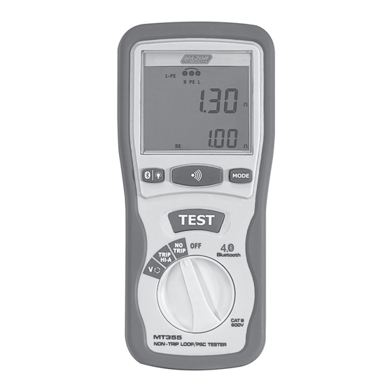
2.2. Meter Description 1 - LCD Display 8 - Loop Impedance Position (High 2 - Bluetooth/Backlight Button current) 3 - Buzzer Button 9 - Volts/Phase Rotation Position 4 - MODE Button 10 - Power Jack 5 - Test Button 11 - Pothook 6 - Rotary Function switch 12 - Battery Cover 7 - Loop Impedance Position... -
Page 7: Display Icons Description
2.3. Display Icons Description - Configuration options, settings you can make within the measurement functions. - Arrows above or below the terminal indicator symbol indicate reversed polarity, check the connection or check the wiring to correct. - Terminal indicator symbol. - Phase Rotation - Primary display and measurement units. -
Page 8: Operation
3.OPERATION 3.1. Voltage and Frequency Measurement 1. Turn the rotary switch to Volts/Phase Rotation Position. 2. Link the test line. 3. Press the MODE Button select terminals (L-PE, L-N, N-PE). • The instrument can automatically distinguish AC and DC voltages, if voltage is AC, The primary (Upper) display shows the AC voltage. -
Page 9: Loop Impedance Measurement
3.3. Loop Impedance Measurement 1. Turn the rotary switch to PSC/HI or NO TRIP Position. 2. Link the test line. 3. Press the MODE Button to select test mode L-N or L-PE. 4. Check the wires state: • Before pushing the TEST Button, certify that the port wiring is correct and that there are port wiring instructions on the screen Figure (1) is •... -
Page 10: Earth Resistance Testing By Loop Method
3.4. Earth Resistance Testing by Loop Method • You can also use the tester to measure the earth resistance component of the total loop resistance. • You can use three leads or the mains cord to perform this test, use the connection shown in Figure below when making a 3-wire connection for earth resistance loop test. -
Page 11: Trip Hi-A Loop Impedance And Prospective Short Current Measurement
3.5. TRIP HI-A Loop Impedance and Prospective Short Current Measurement • If there is a RCD or fuse in the circuit, they must be bridged out prior to testing the loop impedance when using the TRIP HI-A range. • According to IEC 60364, every loop should meet the formula: Ra≤50/Ia Ra: Loop impedance 50: Max of touch voltage... -
Page 12: Backlight
• You can press the Bluetooth/Backlight Button to turn the backlight on or off during use, but it will not turn it off automatically. 3.7. Bluetooth Operation • Download the Major Tech METER-X app on iOS & Android devices. • Hold down the Bluetooth/Backlight button to turn the Blueooth feature ON/OFF. -
Page 13: Specifications
5. SPECIFICATIONS 5.1. Technical Specifications 5.1.1. L-PE (Hi-Amp) Range Resolution Accuracy 0.20 to 19.99Ω 0.01Ω 20.0 to 199.9Ω 0.1Ω ±(3% of reading+6 digits) 200 to 1000Ω 1Ω 1000 to 9999Ω 10Ω ±(3% of reading+60 digits) Measuring Current <15.0A. Voltage Used 195V AC to 265V AC (50/60Hz) 5.1.2. -
Page 14: Ac Voltage
5.1.6. AC Voltage Range Resolution Accuracy 50 to 500V ±(2% of reading+3 digits) 5.1.6. DC Voltage Range Resolution Accuracy 0 to 500V ±(2% of reading+3 digits) 5.1.8. Frequency Range Resolution Accuracy 45 to 65Hz ±2Hz 5.2. General Specifications Range Function Power Source 6x1.5V Size “AA”... - Page 16 MAJOR TECH (PTY) LTD South Africa Australia www.major-tech.com www.majortech.com.au sales@major-tech.com info@majortech.com.au...
Need help?
Do you have a question about the MT355 and is the answer not in the manual?
Questions and answers