Table of Contents
Advertisement
Quick Links
Advertisement
Table of Contents

Related Manuals for Major tech MT574


Summary of Contents for Major tech MT574
- Page 1 INSTRUCTION MANUAL MT574 5kV DIAGNOSTIC HV INSULATION TESTER...
-
Page 3: Table Of Contents
Contents Page no 1. Introduction................... 4 2. Safety Rules and Precautions ............4 3. Structure ..................5 4. Measuring Principle................6 5. Operation Method................6 5.1. Power On/Off................6 5.2. Battery Voltage Check..............7 5.3. DC Voltage Test...............7 5.4. AC Voltage Test...............7 5.5. DC Current Test...............7 5.6. -
Page 4: Introduction
1. INTRODUCTION The MT574 5kV Diagnostic HV Insulation Tester features a large LCD screen with a grey backlight display, along with advanced functionalities such as data storage, data access, alarm, and automatic shutdown. Additionally, it is equipped to measure DC voltage, AC voltage, absorption ratio, and polarization index of DC voltage. - Page 5 Ÿ Pay attention to words and symbols on the tester Ÿ Ensure that the tester and accessories are in good condition before use. There should be no damages or broken parts in the test leads or insulation. Ÿ During measurement, DO NOT touch bare or uninsulated conductors or circuits under measurement.
-
Page 6: Structure
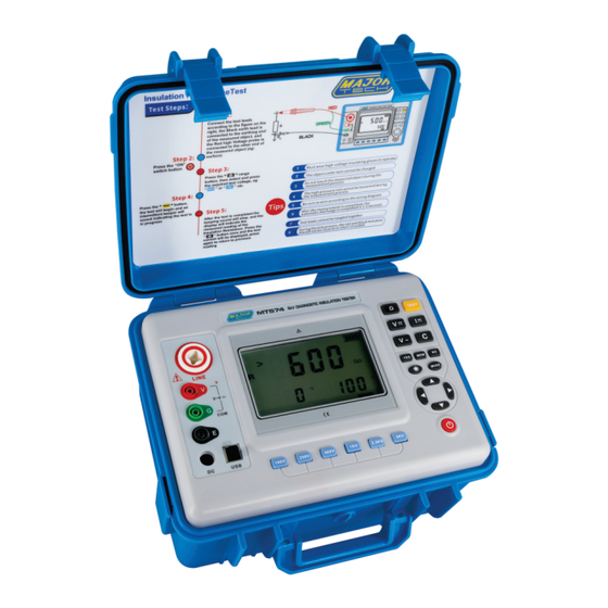
3. STRUCTURE 1 - LCD display screen 2 - LINE interface 3 - V interface 4 - GUARD interface 5 - EARTH interface 6 - Changer interface 7 - USB interface 8 - Voltage select button 9 - Test button 10 - Power on/off button 11 - Security Alligator Clip... -
Page 7: Battery Voltage Check
5.2. Battery Voltage Check After powering on, if the LCD shows a low battery voltage sign " " it indicates that the battery is running low. Please charge timeously. Sufficient battery power will ensure measurement accuracy. 5.3. DC Voltage Test WARNING: Input instrument DC voltage cannot exceed 1000V. -
Page 8: Capacitance Test
2. During the current test, the units of mA are shown in Figure 5-2, and the units of nA, uA, and pA are shown in Figure 5-1. 5.6. Capacitance Test WARNING: Pay attention to standard operation during the capacitor test. Check whether the capacitor is charged before the test. -
Page 9: Insulation Resistance Test
2. The capacitance measurement mode has 4 gears and requires manual shift testing. The first range is 10nf-100nf, the second range is 100nf- 1000nf, the third range is 1uf-10uf, and the fourth range is 10uf-50uf. During the test, the value greater than or less than a certain value needs to be manually switched to the corresponding gear. -
Page 10: Precautions For Testing High Insulation Resistance
6.1. Precautions for testing high insulation resistance. WARNING: After the high-voltage insulation material is added with DC voltage, the current passing through the sample is very small, and it is very susceptible to the influence of external interference, causing large test errors. The higher the measured resistance value, the longer the measurement time. -
Page 11: Guard Use Of Protective Wires
test is completed, press and hold the key to switch the displayed current value, and then press the key to switch back to the resistance value. 7. GUARD USE OF PROTECTIVE WIRES When the insulation resistance of the cable is measured, the leakage current of the covered surface passes through the interior of the insulator and the current converges, resulting in an error in the insulation resistance value. -
Page 12: The Difference Between Polarization Index (Pi) And Absorption Ratio (Dar)
absorption ratio (DAR). As a judgement of the insulation performance, both the polarization index (PI) and the absorption ratio (DAR) indicate the change in the insulation resistance over a period of time after the measured object withstands the measured voltage. 8.2. -
Page 13: Polarization Index (Pi) And Absorption Ratio (Dar) Applications
LCD, "60:15S" as the absorption mode 15 second mode, and "60:30S" as the absorption mode 30 second mode. Small numbers do not show anything for the insulation resistance measurement mode. 4. One end of the test lead (black) is connected to EARTH on the instrument and the other end is connected to the earth end of the circuit under test. -
Page 14: Backlight Control
absorption ratio (or polarization index) decreases after the insulation is wet (see Figure 1), so it is an important indicator of whether the insulation is affected by moisture. It should be pointed out that sometimes the insulation has obvious defects (for example, the insulation breaks down under high pressure), and the absorption ratio or polarization index value is still good. -
Page 15: Data Lock/Storage
value or the insulation resistance value is less than the alarm critical set value and the alarm function is turned on, the instrument flashes the " " symbol and issues a continuous alarm sound. The maximum value of the DC voltage alarm setting is 900V, the maximum value of the AC voltage alarm setting is 700V, and the maximum value of the insulation resistance alarm setting is 9999MΩ.The following figure shows an example ("<"... -
Page 16: Step Adjustment Resistance Measurement Voltage
press key not to delete and return to the data review state, press key to delete the all the stored data. Delete page as shown below: 13. STEP ADJUSTMENT RESISTANCE MEASUREMENT VOLTAGE After powering up, you can modify the voltage value by pressing key at a step value of 50V below the 5KV voltage range, or by pressing key at a step value of 5V. -
Page 17: Specifications
15. SPECIFICATIONS 15.1. Insulation Resistance Range and Accuracy (Measuring function - Insulation Resistance) Output voltage Measuring Range Accuracy Resolution 100V (±10%) 0.05MΩ~0.5MΩ ±3%rdg ± 5dgt 0.001MΩ 0.5MΩ~5MΩ ±3%rdg ± 5dgt 0.01MΩ 5MΩ~50MΩ ±3%rdg ± 5dgt 0.1MΩ 50MΩ~500MΩ ±3%rdg ± 5dgt 1MΩ... -
Page 18: Voltage Range And Accuracy
Remark: Common electrical unit conversion 1 TΩ (Tera ohm) =1000GΩ=10 Ω 1 GΩ (Giga ohm) =1000MΩ=10 Ω 1 MΩ (Mega ohm) =1000KΩ=10 Ω 15.2. Voltage Range and Accuracy Measuring function Measuring Range Accuracy Resolution DC voltage 0.0V~1000V ±1.5%rdg ± 3dgt 0.1V AC voltage 0.0V~750V... -
Page 19: Accessories
The contents of this user manual cannot be used as a reason for using the product for special purposes. Major Tech is not responsible for other losses caused by use. Major Tech reserves the right to modify the contents of the user manual. Subject to change without notice. - Page 20 MAJOR TECH (PTY) LTD South Africa Australia www.major-tech.com www.majortech.com.au sales@major-tech.com info@majortech.com.au...
Need help?
Do you have a question about the MT574 and is the answer not in the manual?
Questions and answers