Advertisement
Quick Links
Advertisement

Related Manuals for Major tech MT902


Summary of Contents for Major tech MT902
- Page 1 INSTRUCTION MANUAL MT902 VDV WIRE TESTER...
- Page 3 Contents Page no...
- Page 4 1. Introduction • The Professional VDV Wire Tester analyzes wiring on phone, computer network and coax cables in one easy step. • The large backlit LCD display maps out connections and describes wiring faults. • The built-in tone generator and the included Video and Data remote identifiers can be used to quickly locate cables in wiring closets and patch panels.
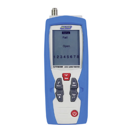
- Page 5 3. Description 3.1. Meter Description 1 - LCD Display 5 - Video Button 9 - Video-F-Connector 2 - Data Button 6 - Tone Button 10 - Voice-RJ11/RJ12 Jack 3 - Voice Button 7 - Tone Button 11 - Data-RJ45 Jack 4 - Cycle Button 8 - Battery Cover...
- Page 6 3.2. Meter Description 1 - Voice-RJ11/RJ12 Jack 2 - Data 1-RJ45 Jack 3 - RJ45 Remote ID’s, Permit Mapping 5 Remote Locations 4 - F-Connector Remote ID’s, Permit Mapping 5 Remote Locations 5 - Data Patch Cable x 2 6 - Coax Patch Cable 3.3.
- Page 7 10 - Indicates wiring error on cable being tested. 11 - Appears when the tone generator is activated. 12 - Indicates that two or more wires are shorted to each other. 13 - Flashes when the tester is connected to a cable with voltage on it, exposure to voltage can damage the tester, if this warning appears, immediately disconnect the cable from the tester.
- Page 8 4.Operation 4-1.Voice WARNING: Exposure to voltage can damage the tester, immediately disconnect the cable under test if the Voltage warning appears on the display. Make sure the cable is not connected to any device that can supply voltage before retesting. Do not connect two different cables into the Voice (RJ11/12) and Data (RJ45) test ports at the same time.
- Page 9 4.1.1.Using the Tone Generator to Trace a Phone Line Note: It is necessary to use a separate amplifier probe. 1. Connect the cable under test to the RJ11/RJ12 port on the tester. 2. Press ON/OFF Button to turn on the tester and then press 3.
- Page 10 4.1.2.Using the Tone Generator to Trace a Phone Line Cont • The connector pins the tone is being sent through will be shown on the bottom of the display. • Repeatedly press the Cycle Button to select the desired pins. •...
- Page 11 USOC Cross Wired Phone Cable Properly Wired • A cross wired cable reverses the connection at one end of the cable. • Pins 1, 6 cross over to pins 6, 1, pins 2, 5 cross over to pins 5, 2, and pins 3, 4 cross over to pins 4, 3.
- Page 12 4.2.Data WARNING: Exposure to voltage can damage the tester. Immediately disconnect the cable under test if the Voltage warning appears on the display. Make sure the cable is not connected to any device that can supply voltage before retesting. Do not connect two different cables into the Voice (RJ11/RJ12) and Data (Rj45) test ports at the same time.
- Page 13 4.2.2. Testing an Installed Data Cable 1. Connect a known good patch cable to the wall port or patch panel of the cable being tested. 2. Connect the other end of the patch cable to the RJ45 port on the tester. 3.
- Page 14 4.3. Testing Shielded Cable • When testing a shielded cable, the Shield indicator will appear on the display if the shield is connected at both ends of the cable. • If the shield is shorted to a wire within the cable, the Shield indicator and the corresponding shorted pin will flash.
- Page 15 4-3-2. Using the Tone Generator to Trace a Data Cable Cont • The pins the tone is being sent through will be shown on the bottom of the display. • Repeatedly press the Cycle Button to select the desired pins. •...
- Page 16 4.3.3. Cable Identification on Installed Data Cable • The remote ID’s can be used to identify cable runs from the patch panel to a wall port. • Each identifier has a labeled ID number. • When the tester is connected to a cable that has an identifier attached at the other end, the tester will display the ID number that is marked on the identifier.
- Page 17 4.3.4. Wiring and Display Examples for Data Cable T568B Data Cable Properly Wired • Pass appears on the display indicating a properly wired cable. • The pin numbers on the top row agree with the bottom row indicating proper continuity. Notes: Both the T568A and T568B wiring standard will test the same as long as the same standard is used on both ends of the cable.
- Page 18 T568B Data Cable With Split Pairs • There is a split between the pairs on pins 3, 4 and 5, 6. • Fail and Split appear on the display and the pin numbers with the split will flash. T568B Data Cable With a Shorted and Open Pair •...
- Page 19 T568B Data Cable With Reversed Pair and Crossed Connection • The pair on pins 1 and 2 is reversed and the wires on pins 5 and 6 are crossed at one end of the cable. • Fail will appear on the display indicating a defective cable, the pins with wiring errors will flash.
- Page 20 4.4. Video Testing Wiring on Coax Patch Cables Terminated with F Connectors. Note: Test signals in the Video mode may not pass through a splitter. Only one remote ID can be connected at a time when testing cables connected to a common splitter. 4.4.1.
- Page 21 4.4.2. Tone Tracing on Coax Cable Note: It is necessary to use a separate amplifier probe. Certain splitters used on Coaxial cables will prevent the tone from passing. 1. Connect the cable under test to the F connector on the tester.
- Page 22 4.4.3. Tone Tracing on Coax Cable Cont • The tone can be sent through the center conductor, the shield or both. • Repeatedly press the Cycle Button to select the desired conductors. • The selection will be shown on the bottom of the display, refer to sequence chart below for explanation.
- Page 23 4.4.4. Cable Identification on Installed Video Cable • The remote ID’s can be used to identify cable runs from the patch panel to a wall port, each identifier has a labeled ID number. • When the tester is connected to a cable that has an identifier attached at the other end, the tester will display the ID number that is marked on the identifier.
- Page 24 4.4.5. Wiring and Display Examples for Coax Cable Coax Cable with Proper Continuity • The cable is good and passes the test, ID 1 signifies that Remote Identifier number 1 is being used to terminate the cable. • The flashing “o” s on the bottom of the display indicate the tester is running a continuous test.
- Page 25 4.5. Battery Replacement 1. Pull down locking tab, and open the battery door. 2. Replace the 2 x AA battery. 3. Re-assemble the meter. Note: Do not operate the tester with the battery cover removed.
- Page 28 MAJOR TECH (PTY) LTD South Africa Australia www.major-tech.com www.majortech.com.au sales@major-tech.com info@majortech.com.au...
Need help?
Do you have a question about the MT902 and is the answer not in the manual?
Questions and answers