Table of Contents
Advertisement
Quick Links
Advertisement
Table of Contents

Subscribe to Our Youtube Channel
Related Manuals for Major tech MT933


Summary of Contents for Major tech MT933
- Page 1 INSTRUCTION MANUAL MT933 CABLE LENGTH TESTER...
-
Page 3: Table Of Contents
Contents Page no 1. Description..................4 2. Safety Instructions................4 3. General Description................4 4. Meter Description................5 4.1. Instrument Description..............5 4.2. Symbols and Annunciators............6 4.3. Accessories Provided..............6 5. Description of Function Keys...............6 5.1. Backlight Button...............6 5.2. Hold Button................6 5.3. MEM Button................7 5.4. CAL Button................7 5.5. -
Page 4: Description
1. DESCRIPTION • The Cable Length Meter is a hand-held testing device with the following measurement capabilities: resistance, temperature and length. • They can be used as mΩ meters to measure precise bonding resistances. • The primary function of these meters is to calculate the length of cable based upon its material, temperature, and cable gauge, Cable material type can be either uncoated copper or aluminum. -
Page 5: Meter Description
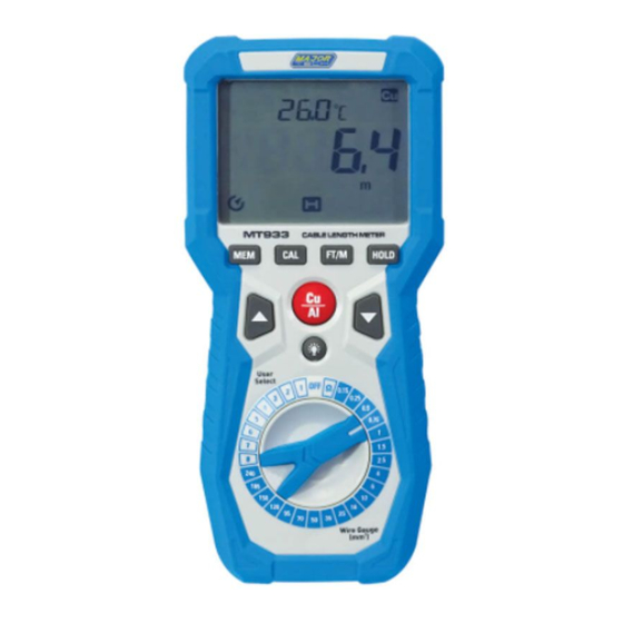
2. Eight memory locations in user select mode. 3. mΩ resistance test mode. 4. Measures copper and aluminum cables. 5. Ambient temperature testing provides automatic compensation for measurements. 4. METER DESCRIPTION 4.1. Instrument Description 1 - LCD Display 12 - Lanyard Hole 15 - Black Input Terminal 2 - MEM Button 13 - Battery Cover... -
Page 6: Symbols And Annunciators
4.2. Symbols and Annunciators 1 - Used to save data or for confirmation 10 - ln user select mode 2 - Temperature 11 - kilo meter foot 3 - Celsius and Fahrenheit units 12 - Data Hold 4 - Low Resistance 13 - ERROR 5 - Copper 14 - Auto Power Off... -
Page 7: Mem Button
5.3. MEM Button • The MEM Button is used for the user-selected programming function. • Refer to "Operation" for a complete description of the programming process. • Press and hold the MEM Button to cancel the auto-shutdown function. 5.4. CAL Button •... -
Page 8: Operating
6. 0PERATING WARNING: Do not connect the unit to live voltage. 6.1. Calibration Procedure 1. Each time the meter is turned ON, it should be calibrated before use. 2. Set the rotary switch from the OFF to O Position. 3. Connect the two leads for the red set of Kelvin clips are plugged into the red terminals on the meter;... -
Page 9: Measuring Length Of Wire
5. Press the CAL Button, the display alternately shows " " and " "; flash twice each time. Press the MEM Button, if the display briefly shows " " and then the meter returns to resistance measurement mode, the calibration succeeds. 6.lf the display show "... - Page 10 9 . The display shows the length of the wire. 10. When the measurements finishes, remove the alligator clips from the wire. Typical Configuration 6 10...
-
Page 11: User Select Mode
6.3. User Select Mode • The use select mode allows user to save the resistance parameter of a user wire for length measurements of the wires of the same kind(Same gauge and same conductor material). • In addition, it enables user to accurately measure the length of standard gauge wires. -
Page 12: Measure The Length Of Cable In User-Defined Mode
9. Press the upper end of the Up/Down Button to increase or the lower end of this button to decrease the reading on the display in 0.1 increments or decrements, adjust the reading until it equals the length of the sample wire to measured. 10. -
Page 13: Clear Memory Locations In User Select Mode
6.6. Clear memory locations in user select mode 1. Disconnect the Kelvin Clips from the cable under test. 2. The knob selects the user-custom gear that needs to be cleared. 3. Press CAL Button to display " ". Press the MEM Button again, the meter will erase the stored data in the selected memory location and the meter will return to measurement mode and the selected memory location is empty. -
Page 14: Maintenance
7. MAINTENANCE WARNING: Before opening the case, remove the test leads from the circuit and shut off the unit. This Meter is designed to provide years of dependable service, if the instructions below are followed: • Keep the meter dry. If it gets wet, wipe it off. •... -
Page 15: Specifications
9. SPECIFICATIONS 9.1. Technical Specifications Function Range Resolution Accuracy Protection against overcharge Length 1 000m 0.1m ±(1% reading+1ml) Measurement 10 000m ±(1% reading+1ml) Max 60V Range 30km 0.01km ±(1.2% reading+1ml) Overload 1 000ft 0.1ft ±(1% reading+3ft) Protection 10 000ft ±(1% reading+1ft) 100kft 0.01ft ±(1.2%reading+1ft) - Page 16 MAJOR TECH (PTY) LTD South Africa Australia www.major-tech.com www.majortech.com.au sales@major-tech.com info@majortech.com.au...
Need help?
Do you have a question about the MT933 and is the answer not in the manual?
Questions and answers