
Related Manuals for SMC Networks ZL112A Series


Summary of Contents for SMC Networks ZL112A Series
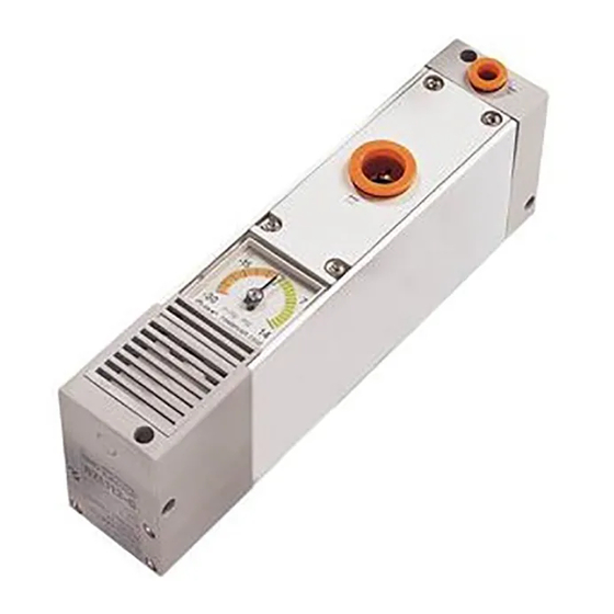
- Page 1 Document No.ZL-OM01001 PRODUCT NAME Multistage Ejector MODEL / Series / Product Number ZL112A Series...
-
Page 2: Table Of Contents
Document No.ZL-OM01001 Contents Safety Instructions Model Indication and How-to-Order Names of Parts Operating Environment Mounting and Installation Air Supply Piping Electrical wiring Solenoid valve Vacuum pressure switch Construction Maintenance and Inspection Exhaust from ejector Specifications Circuit diagram Exhaust characteristics, flow characteristics, time required to reach the specified vacuum, release flow characteristics Flow characteristics curve Troubleshooting... -
Page 3: Safety Instructions
Document No.ZL-OM01001 Safety Instructions These safety instructions are intended to prevent hazardous situations and/or equipment damage. These instructions are categorized into three groups, "Caution", "Warning" and "Danger" depending on the level of hazard and damage, and the degree of emergency. They are all important notes for safety and must be followed in addition to International Standards (ISO/IEC), Japan Industrial Standards (JIS) and other safety regulations... - Page 4 Document No.ZL-OM01001 Safety Instructions Caution 1. The product is provided for use in manufacturing industries. The product herein described is basically provided for use in manufacturing industries. If the product is being considered for use in other industries, consult SMC beforehand and exchange specifications or a contract if necessary.
- Page 5 Document No.ZL-OM01001 ■Explanation of Symbols Symbol Definition Things you must not do. Instructions are provided as a drawing or sentence next to the symbol. Things you must do Instructions are provided as a drawing or sentence next to the symbol. ■Operator 1.
- Page 6 Document No.ZL-OM01001 ■Safety Instructions Warning Do not disassemble, modify (including the replacement of board) or repair other than instructed in this manual. Otherwise, an injury or failure can result. Disassembly prohibited Do not operate the product outside of the specifications. Do not use for flammable or harmful fluids.
- Page 7 Document No.ZL-OM01001 Caution Do not touch the terminals and connectors while the power is on. Otherwise electric shock, malfunction or damage to the switch can result. Do not touch Perform sufficient trial run. Otherwise, injury or damage to the system can result due to suction failure depending on the conditions of the suction of the workpiece or the pressure switch settings.
-
Page 8: Model Indication And How-To-Order
Document No.ZL-OM01001 Model Indication and How to Order - 7 -... -
Page 9: Names Of Parts
Document No.ZL-OM01001 Names of Parts Without valve Supply ( P ) Port Vacuum ( V ) Port Silencer case ( Exhaust ) Suction cover With Vacuum With digital vacuum With Vacuum port adapter With port exhaust pressure gauge pressure switch Vacuum pressure detection port Port block... -
Page 10: Operating Environment
Document No.ZL-OM01001 Operating Environment - Do not use in an environment where corrosive gases, chemicals, sea water, water or steam are present. These can cause failure or malfunction. - Do not use the product in a place where the product could be splashed by oil or chemicals. If the product is to be used in an environment containing oils or chemicals such as coolant or cleaning solvent, even for a short time, it may be adversely affected (damage, malfunction, or hardening of the lead wires). -
Page 11: Mounting And Installation
Document No.ZL-OM01001 Mounting and Installation 1. Tighten the body to the recommended tightening torque (For top and side mounting: 1.2 to 1.5N・m, for bottom mounting: 0.60 to 0.74 Nm ). If the recommended tightening torque is exceeded, the body, mounting screws and brackets may be damaged. Insufficient torque can cause displacement of the body from its proper position and the looseness of the mounting screws. -
Page 12: Air Supply
Document No.ZL-OM01001 Supply air 1. For the compressed air quality, refer to 2.4.3, 2.5.3 and 2.6.3 of ISO8573-1:2001 (JIS B8392-1:2003). 2. It is recommended that an air filter and a mist separator are connected to the upstream side of the ejector and the pump system. (Refer to Air Preparation Equipment Selection Guide in Best Pneumatics 5 for detail.) 3. -
Page 13: Piping
Document No.ZL-OM01001 Piping ■ Piping for Air Pressure Supply and Vacuum Pressure Supply (1) Preparation before piping Before piping, perform air blow (flushing) or cleaning to remove any cutting chips, cutting oil, Wrap this way. dust, etc. from the piping. (2) Wrapping of pipe tape When installing piping or a tube fitting into a port, prevent cutting Sealant tape... - Page 14 Document No.ZL-OM01001 ■ Piping to the Vacuum (V) Port (1) Allow a sufficient margin of tube length when piping, in order to prevent twisting, tensile, moment loads, vibration or impact being applied to the tubes and fittings. This can cause damage to the tube fittings and crushing, bursting or disconnection of tubing.
-
Page 15: Electrical Wiring
Document No.ZL-OM01001 Electrical wiring 1. Use the specified voltage. Otherwise failure or malfunction can occur. 2. Do not exceed the specified maximum allowable load. Otherwise it can cause damage or shorten the life of the product. 3. Design the product to prevent reverse current when the circuit is opened or the product is forced to operate for operational check. -
Page 16: Solenoid Valve
Document No.ZL-OM01001 Solenoid Valve 1. Avoid energizing the solenoid valve for long periods of time. If a solenoid valve is continuously energized for an extended period of time, the heat generated by the coil assembly may reduce performance and life of the valve or have adverse effects on peripheral equipment. Therefore, when it is continuously energized for an extended period of time or when the energized period per day is longer than the de-energized period, use N.O. -
Page 17: Construction
Document No.ZL-OM01001 Construction Without valves and switch With valves and switch Components Description Material Note Body assembly Resin, NBR, Steel Suction cover assembly Resin, NBR, Steel, (Filter element included) Non-woven fabric Silencer case assembly (Sound absorbing Resin, Steel For silencer exhaust material and clip included) Port block assembly Aluminum alloy, NBR, Steel... -
Page 18: Maintenance And Inspection
Document No.ZL-OM01001 Maintenance and Inspection ■ Implement the maintenance and check shown below in order to use the ejector and the vacuum system safely and in an appropriate way for a long period of time. 1. Maintenance should be performed according to the procedure indicated in the Operation Manual. - Page 19 Document No.ZL-OM01001 Replacement parts list Description Part number Note Suction cover assembly ZL112A-FC1□-A □: Vacuum port size Nil: ø12, N: ø1/2" (Filter element included) Silencer case assembly (Sound absorbing ZL112A-SC1-A For silencer exhaust material and clip included) Port block assembly For port exhaust ZL112A-EP1□-A (Clip included)
- Page 20 Document No.ZL-OM01001 How to Order Replacement Parts Supply valve/Release valve How to order connector assembly Digital vacuum pressure switch リード Lead wire assembly with connector How to order - 19 -...
- Page 21 Document No.ZL-OM01001 ■Replacement Procedure for Filter element (ZL112A-FE1-A) The suction cover can be attached or detached at a touch. Suction cover can be removed by pushing the suction cover levers (2 pcs.) on the side. (It can be removed from the opposite side as well.) Replace the filter element assembled in the filter case.
-
Page 22: Exhaust From Ejector
Document No.ZL-OM01001 ■Removal/Mounting of the Solenoid Valve or Pressure Switch Connector Do not attempt to insert or pull out the connector while the power is on. Otherwise, it may cause switch output malfunction. Before removal or mounting of the pressure switch connector, it is necessary to remove the silencer assembly (exhaust block assembly). -
Page 23: Specifications
Document No.ZL-OM01001 Specifications ■ Ejector Specifications *1 Values are at the standard supply pressure and based on SMC’s measurement standards. They depend on atmospheric pressure (weather, altitude, etc.) and the measurement method. *2 10 to 500 Hz for 2 hours in each direction of X, Y, and Z (De-energized, Initial value) *3 3 times in each direction of X, Y, and Z (De-energized, Initial value) ■... - Page 24 Document No.ZL-OM01001 ■ Digital Vacuum Pressure Switch Specifications Note 1) If the applied voltage fluctuates around the set value, the hysteresis must be set to a value more than the fluctuating width, otherwise chattering will occur. Note 2) When the analog voltage output is selected, the analog current output cannot be selected simultaneously. Note 3) When the analog current output is selected, the analog voltage output cannot be selected simultaneously.
-
Page 25: Circuit Diagram
Document No.ZL-OM01001 Circuit diagram Port exhaust Without valve ZL112AP□ ZL112A With vacuum pressure gauge With vacuum port adapter ZL112A-G ZL112A-GN With digital vacuum pressure switch ZL112A-D□□□ - 24 -... - Page 26 Document No.ZL-OM01001 With supply valve and release valve With supply valve ZL112A-K1□□□□ ZL112A-K2□□□□ ZL112A-B1□□□□ ZL112A-B2□□□□ Exhaust Characteristics/Flow Rate Characteristics/Time to Reach Vacuum Vacuum Break Flow Adjusting Needle - 25 -...
-
Page 27: Flow Characteristics Curve
Document No.ZL-OM01001 Flow Characteristics Curve ■ How to read the flow characteristics curves of ejector The flow characteristics curve shows the relationship between the vacuum pressure and the suction flow of the ejector/vacuum pump system. It shows that the vacuum pressure changes when the suction flow changes. -
Page 28: Troubleshooting
Document No.ZL-OM01001 Troubleshooting ■Problems when using ejector/ vacuum pump system and troubleshooting Trouble Cause Countermeasures Initial The adsorption area is too small; Increase the lifting force. → Increase the pad diameter adsorption the adsorption force is not strong → Increase the number of pads. failure enough compared with the weight (It fails to... - Page 29 Document No.ZL-OM01001 Trouble Cause Countermeasures → Reduce the internal capacity of the vacuum Adsorption Internal capacity of the circuit on response the vacuum side is too large for circuit. → Change to an ejector with larger suction flow. is not the ejector performance.
- Page 30 Document No.ZL-OM01001 Trouble Cause Countermeasures → Replace the vacuum pad with a new one. Vacuum Adsorbing part has some problem, → Revise the adsorption conditions (such as failure such as deterioration of the vacuum over time pad, or leakage due to frictional compatibility of the vacuum pressure with the (absorbs wear.
- Page 31 Document No.ZL-OM01001 If the countermeasures above are not effective, there may be some problem with the product. In that case, stop using the product immediately without disassembling or repairing it. If any of the examples below are applicable, there may be a problem with the product. 1) It was used with a voltage other than the rated voltage.
- Page 32 Document No.ZL-OM01001 Revision history 4-14-1, Sotokanda, Chiyoda-ku, Tokyo 101-0021 JAPAN Tel: + 81 3 5207 8249 Fax: +81 3 5298 5362 http://www.smcworld.com Note: Specifications are subject to change without prior notice and any obligation on the part of the manufacturer. ©...
Need help?
Do you have a question about the ZL112A Series and is the answer not in the manual?
Questions and answers