Table of Contents
Advertisement
Quick Links
Advertisement
Table of Contents

Related Manuals for Strata SLR PRO Series


Summary of Contents for Strata SLR PRO Series
- Page 1 SLR PRO SERIES LASER WELDER USER MANUAL SLR 3000 SLR 4000 SLR 5000...
-
Page 2: Table Of Contents
SLR PRO SERIES LASER WELDER Table of Contents Chapter 1 Overview ..................... 3 Chapter 2 Safety Information ................5 Chapter 3 Welder Description ................11 Chapter 4 Setup of the Welder ................18 Chapter 5 Operating Features of the Welder ............23... -
Page 3: Chapter 1 Overview
SLR PRO SERIES LASER WELDER Chapter 1 Overview 1.1 Introduction The SLR Series handheld laser welding system integrates laser light source, cooling module, welding gun and control module, and outputs high definition 1080nm laser. Because 1080nm laser is invisible light, operators should be aware of the danger of laser and operate the equipment according to the User Guide to avoid personal injury. - Page 4 SLR PRO SERIES LASER WELDER 1.3 Product Packaging and Unpacking The handheld welding system is packaged within a cardboard box secured with PET packing strip, as shown in the following figure: Figure 1-2 Schematic Diagram of Product Packaging To unpack the unit from the cardboard box, cut off the packing strip, take out the foam board first and then remove the external box.
-
Page 5: Chapter 2 Safety Information
SLR PRO SERIES LASER WELDER Chapter 2 Safety Information 2.1 Laser Safety Level The SLR laser welder series of output invisible laser radiation with a wavelength of 1080nm or near 1080nm, According to the definition in IEC/EN 60825-1, lasers in such series belong to Class 4 laser products. - Page 6 SLR PRO SERIES LASER WELDER 2.2.3 Non Beam Hazard SLR handheld laser welder series are powered by 230V AC. Ensure that the power supply has been connected to the protective ground, otherwise it may cause equipment damage and personal injury.
- Page 7 SLR PRO SERIES LASER WELDER 2.4 Laser Radiation Protection 2.4.1 Requirements for Laser Radiation Protection Because the laser radiation with a wavelength of 1080nm light emitted by the laser is invisible radiation of high power, even the scattered light can still cause irreversible damage to the eyes.
- Page 8 SLR PRO SERIES LASER WELDER • Personnel safety management must develop and maintain a training and assessment mechanism to ensure the employee of the user meet the safety requirements and strengthen their safety awareness. 2.5 Safe Operation of Equipment 2.5.1 Requirements for Laser Welding Operation Environment...
- Page 9 SLR PRO SERIES LASER WELDER 2.5.3 Instructions to Optical Operation We strongly recommend that you read the following operating instructions before operating the equipment: 1. Protective glass shall be installed during welding to avoid contamination of the focusing lens inside the hand-held welding gun;...
- Page 10 SLR PRO SERIES LASER WELDER 1. When using the handheld laser welder, please ensure that the equipment is well grounded; otherwise the housing may be charged and may cause personal injury; 2. Ensure the power supply connected to the equipment is connected to its protective ground before putting into use;...
-
Page 11: Chapter 3 Welder Description
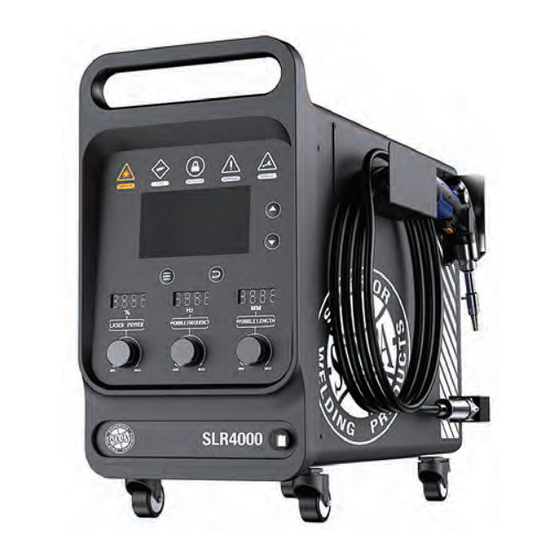
SLR PRO SERIES LASER WELDER Chapter 3 Welder Description 3.1 Accessories of the Welder The shipping list of the SLR series welders are as follows: Table 3-1 Shipping List of a SLR Series Welders Quick Start Guide Work/Earth lead 3.2 Product Specifications... - Page 12 SLR PRO SERIES LASER WELDER 3.3 Description of Welders 1. Air Outlet 3. Welding Gun 2. Front Panel 4. Air Inlet 5. Caster...
- Page 13 SLR PRO SERIES LASER WELDER 3.4 Front Panel Emission...
- Page 14 SLR PRO SERIES LASER WELDER 3.5 Rear Panel 230V...
- Page 15 SLR PRO SERIES LASER WELDER 3.6 Welding Gun...
- Page 16 SLR PRO SERIES LASER WELDER 3.7 Dimension Drawing of the Welder...
- Page 17 SLR PRO SERIES LASER WELDER...
-
Page 18: Chapter 4 Setup Of The Welder
SLR PRO SERIES LASER WELDER Chapter 4 Setup of the Welder 4.1 Preparation Before Setup Setup Description: 1. External interlock device connection: the welder is provided with an external interlock connector for connecting external interlock safety devices (such as safety pedal and external emergency stop lamp);... - Page 19 SLR PRO SERIES LASER WELDER 4.2 Setup Space and Heat Dissipation Airflow Requirement Precautions: 1. Air inlet at the bottom: the air inlet is provided at the bottom of the welder. Please ensure that the space under the welder is unobstructed.
- Page 20 SLR PRO SERIES LASER WELDER The work lead is secured with M8 screws. Gas inlet connector is a Φ 12 quick connector. The input gas pressure should be between 0.15Mpa (22psi) and 0.3MPa (44psi). 4.4 Connecting External Interlock Signals Connect the external interlock safety device as required. If there is no external safety device, the connector shall be short circuited.
- Page 21 SLR PRO SERIES LASER WELDER 4.6 Startup of Welder (1) Prepare for equipment installation according to 4.1 - 4.5; (2) Start 230V power supply; (3) Press the Startup button at the top right of the welder, as shown in the following figure:...
- Page 22 SLR PRO SERIES LASER WELDER 4.7 Shut Down the Welder Follow following steps to shut down the welder: (1) Release the Laser Output button of the welding gun to stop outputting laser; (2) Remove the workpiece clamp; (3) Pop up the Startup button to shut down the welder;...
-
Page 23: Chapter 5 Operating Features Of The Welder
SLR PRO SERIES LASER WELDER Chapter 5 Operating Features of the Welder 5.1 Front Panel Indicator Information (1) Emission indicator: it displays whether the welder is outputting laser. It turns yellow when outputting laser; otherwise it turns off; (2) GAS indicator: It turns yellow when there is no gas input or the air pressure is insufficient;... - Page 24 SLR PRO SERIES LASER WELDER (3) Warning information bar: displays the current warning information of the welder; (4) Operation information: displays the functions of the operation buttons below. 5.3 Features for process Package Switching The operation of switching process package is as follows: (1) Short press a Previous button: switch to the previous process package;...
- Page 25 SLR PRO SERIES LASER WELDER 5.4 Operating Buttons According to the LCD prompts, the functions of the operating buttons are as follows: (1) Left button: Press it to store the welding package, i.e., store the parameters of active welding package;...
- Page 26 SLR PRO SERIES LASER WELDER 5.5 Power Adjustment The digital display will display the power percentage of the active process package. The operation of adjusting the power as follows: 1. Rotate the knob clockwise and the power percentage will be increased;...
- Page 27 SLR PRO SERIES LASER WELDER (2) Rotate the knob counterclockwise and the wobble frequency will be decreased; The range of wobble frequency adjustment is 0 - 200hz. When the wobble frequency is 0Hz, there will be no wobble. 5.7 Wobble Length Adjustment The digital display tube will display the wobble length of the active process package;...
-
Page 28: Chapter 6 Welding
SLR PRO SERIES LASER WELDER Chapter 6 Welding 6.1 Key Safety Features 6.1.1. Safety Interlock of Nozzle Tip and Work Lead During welding, only when the nozzle tip and the work lead form a closed circuit, the laser is allowed to output. Before welding, the work lead should be attached to the workpiece. - Page 29 SLR PRO SERIES LASER WELDER 6.3 Use and Replacement of Welding Nozzle Tips The welder is provided with a variety of welding nozzle tips for users to replace; The steps for installing the copper nozzle tip are as follows: (1) Insert the copper nozzle into the air tube;...
- Page 30 SLR PRO SERIES LASER WELDER Removing Cover Glass Lid Taking out Cover Glass Unscrew the Hand-turn Screw and Remove the Cover Glass After Removing Cover Glass Lid, Turn the Hand-turn Screw Lid. into the thread hole in the middle of Cover Glass, then lift it up.
- Page 31 SLR PRO SERIES LASER WELDER Wire Feeding Rotating Component Installing Wire feeding Spring Tube Assembling Tighten the Set Screw Insert Wire feeding Spring Tube Clamper through the Wire feeding Spring Tube, insert the Wire feeding Spring Tube into Install the parts in the correct order.
- Page 32 SLR PRO SERIES LASER WELDER Dismantling Gun Barrel and Cover Dismantling Gun Head Part Glass Lid countersink screw Dismantle the parts in sequence shown. Dismantle the parts in sequence shown. Note: Before Dismantling, make sure to loosen the countersink screw on the gun head.
- Page 33 SLR PRO SERIES LASER WELDER 6.5 Use and Cleaning of the Filter Screen During the long-term use of the welder, the filter screen at its bottom is susceptible to buildup of a large amount of dust, resulting in the decline of heat dissipation effect and temperature failure;...
- Page 34 SLR PRO SERIES LASER WELDER 6.6 Use and Replacement of Feeder Tube Holder During the long-term use of the welder, the filter screen at its bottom is susceptible to buildup of a large amount of dust, resulting in the decline of heat dissipation effect and temperature failure;...
-
Page 35: Chapter 7 Defining Welding Process Package
SLR PRO SERIES LASER WELDER Chapter 7 Defining Welding Process Package 7.1 Preset Process Package The welder has various preset process packages, all of which have been verified and can be directly accessed for use. Table 7-1 Details of Preset Process Packages in SLR 5000 Handheld Welder Table 7-2 Details of Preset Process Packages in SLR 4000 Handheld Welder 7.2 Quickly Setting of Customized Process Packages... - Page 36 User only needs to switch to the customized process package next time. 7.3 Detailed Setting of Customized Process Package The user can set all parameters of the customized process package in detail through the Wechat APP of STRATA SLR; Refer to the following figure for details; STRATA SLR...
- Page 37 SLR PRO SERIES LASER WELDER The specific setting process is as follows: (1) Use Wechat to scan the QR code on the welder and enters the SLR’s APP; (2) Open the bluetooth of mobile phone, enter the “Device” interface of APP, and connect the device;...
- Page 38 SLR PRO SERIES LASER WELDER...
-
Page 39: Chapter 8 Fault Information And Location
SLR PRO SERIES LASER WELDER Chapter 8 Fault Information and Location 8.1 Fault Display If any fault occurs to the welder, the corresponding indicators will go on, and the LCD screen will display the fault information as shown in the figure below. - Page 40 SLR PRO SERIES LASER WELDER...
- Page 41 SLR PRO SERIES LASER WELDER 8.4 Abnormalities and Troubleshooting...
-
Page 42: Chapter 9 Handheld Laser Weld Torch Accessories And Spare Parts
SLR PRO SERIES LASER WELDER Chapter 9 Handheld Laser Weld Torch Accessories and Spare Parts 6. Lens cover screw 8. Focusing lens pressure ring 7. Protective lens 9. Vibrating mirror motor 5. Protective lens cover 10. Focusing lens 4. Gun barrel clamping nut 3. - Page 43 SLR PRO SERIES LASER WELDER Photo Diagram Part SKU/Part Sales Comment Brand Number Number Description C100 Copper Nozzle Used for non wire Strata Type C100 feeding external fillet welding D100 Copper Nozzle Used for non wire Strata Type D100 feeding...
- Page 44 SLR PRO SERIES LASER WELDER Photo Diagram Part SKU/Part Sales Comment Brand Number Number Description G120 Copper Nozzle Strata Type G120- 1.2mm G160 Copper Nozzle Strata Type G160- 1.6mm CN358 Cutting Nozzle Cutting Nozzle Strata CN358 CN1612 Copper Nozzle Strata...
- Page 45 SLR PRO SERIES LASER WELDER...
- Page 46 SLR PRO SERIES LASER WELDER...
-
Page 47: Chapter 10 Warranty
SLR PRO SERIES LASER WELDER Chapter 10 Warranty As part of an on-going commitment to excellence in Warranty does not cover pre delivery service and product support, Euroquip offers a comprehensive adjustment, or failure that may occur as a result of product warranty program. - Page 48 STRATA should be notified in time for troubleshooting such fault. Any product returned to STRATA for repair or replacement shall be placed in the original packaging provided by STRATA. Otherwise, STRATA is entitled to paid repair service of any product suffering any damage caused thereby.
Need help?
Do you have a question about the SLR PRO Series and is the answer not in the manual?
Questions and answers