Table of Contents
Advertisement
Quick Links
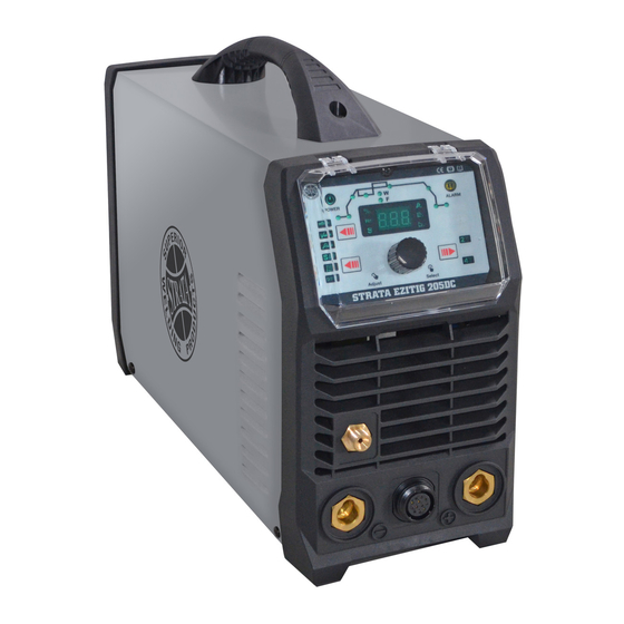
EZITIG 205DC
INVERTER WELDER
OPERATING INSTRUCTIONS
IMPORTANT!
To qualify for full 24 month warranty, you must register within 30 days of purchase. See inside for details.
Read these Operating Instructions Completely before attempting to use this machine. Save this manual and keep
it handy for quick reference. Pay particular attention to the safety instructions we have provided for your
protection. Contact your distributor if you do not fully understand anything in this manual.
230V 50HZ
IGBT
DIRECT
IP23 CORROSION
SPIKE/
INTELLIGENT
SINGLE
INVERTER
CURRENT
& SALT SPRAY
GENERATOR
PROTECTION
PHASE
TECHNOLOGY
OUTPUT
RESISTANT
SAFE
SYSTEM
www.strata.co.nz
Advertisement
Table of Contents
Troubleshooting

Subscribe to Our Youtube Channel
Related Manuals for Strata EZITIG 205DC


Summary of Contents for Strata EZITIG 205DC
- Page 1 EZITIG 205DC INVERTER WELDER OPERATING INSTRUCTIONS IMPORTANT! To qualify for full 24 month warranty, you must register within 30 days of purchase. See inside for details. Read these Operating Instructions Completely before attempting to use this machine. Save this manual and keep it handy for quick reference.
-
Page 2: Table Of Contents
EZITIG 205DC CONTENTS 1. EZITIG205DC Related Parts ..........6 2 Overview ..................7 2.1 Features ........................7 2.2 Technical Data ......................7 2.3 Brief Introduction ......................8 2.4 Duty cycle and Over-heat ..................2.5 Working Principle ......................10 2.6 Volt-Ampere Characteristic ..................10 3 Installation & Operation ............12 3.1 Layout for the front and rear panel .................12... - Page 3 EZITIG 205DC 3.6 Operation environment ..................... 3.7 Operation Notices ...................... 4 Maintenance & Troubleshooting ..........4.1 Maintenance ....................... 4.2 Troubleshooting ......................4.3 List of error code......................4.4 Electrical schematic drawing ..................43 Safety .................... Warranty ..................www.strata.co.nz...
- Page 4 EZITIG 205DC Congratulations on the purchase of your new Stata Welding Product! The Strata range of Welding Products from Euroquip utilises the latest design technology and is engineered to produce welding products that combine market leading value, features and durability.
- Page 5 • EZITIG 205DC • INVERTER TIG WELDER The EZITIG 205DC is a powerful highly portable, easy to use machine. Extreme stress tested to 440V with IP23 protection, the EZITIG 205DC is built to last in the harshest NZ work environments.
-
Page 6: Ezitig205Dc Related Parts
Earth Lead 25mm2 cable, 35-70mm plug, 3m 300A Heavy duty earth clamp Regulators GR101ARFL Argon regulator c/w flow tube GR101AR-2FL Argon regulator c/w twin flow tubes Gas Hose SW17844 Gas hose coupling For Gas lens Parts Please see the Strata Consumables Guide. www.strata.co.nz... -
Page 7: Overview
EZITIG 205DC 2 Overview 2.1 Features Lift TIG and HF Start Modes for versatility when welding around sensitive electronic equipment. Adjustable arc force, hot start & anti stick control for greater control and ease of use when MMA welding. -
Page 8: Brief Introduction
EZITIG 205DC 35% 200A Duty cycle 40℃ 10 60% 155A 100% 120A Welding Current 5-200 Range (A) Up slope/Down slope 0-10 Pre/Post Flow (S) 0-2/0-10 Pulse frequency (HZ) 0.5-200 Pulse width range (%) 5-95 No Load Voltage(V) Efficiency(%) ≥85% Power Factor 0.75... -
Page 9: Duty Cycle And Over-Heat
EZITIG 205DC ★ High performance MCU, Digital control, Digital display ★ Preset all parameters with hold process ★ HF/Lift TIG, current down slope and up slope, gas post-flow, Pulse Frequency ★ Intelligent protection: over-voltage, under-voltage, over-current, over-heat 1. For MMA, polarity connection can be chosen according to different electrodes,please refer to §3.3.1;... -
Page 10: Working Principle
EZITIG 205DC The relation between the duty cycle “X” and the output welding current “I” is shown as the right figure. If the welding machine is overheating, the IGBT over-heat protection sensing will send a Relation of welding current and... - Page 11 EZITIG 205DC current I is as follows: When I ≤600A,U =10+0.04 I (V) ;When I >600A,U =34(V). (V) Volt-ampere characteristic The relation between the conventional loading Working voltage and welding current point (A) www.strata.co.nz...
-
Page 12: Installation & Operation
EZITIG 205DC 3 Installation & Operation 3.1 Layout for the front and rear panel (1) “-” Output terminal. TIG torch remote connection socket. (2) (3) TIG gas connection. (4) “+” Output terminal. (5) Power switch (6) Input power cable. (7) Inlet gas connector. - Page 13 EZITIG 205DC *Denotes more detailed explanation of function to follow. Further Controls Explained TIG HF/ Lift Ignition Modes (10,11) For TIG welding process, contact of the torch tungsten to the workpiece will cause contamination of the tungsten and the workpiece that will adversely affect the weld quality, especially when the tungsten is electrically energised.
- Page 14 EZITIG 205DC Before welding displays the setting selected/being adjusted using the control knob (22). During welding, displays welding current. The parameter setting displayed is indicated by the LEDs 15, 16, 17,19,20,21. If left inactive for several seconds, display will revert back to main welding current setting.
- Page 15 EZITIG 205DC Sets the main welding current . Unit(A) and setting range (5-200A). Base current setting indicator (5) Only available when pulse mode (12) is selected. Sets the current of the low/ base pulse. Unit(A) and setting range (5-200A). Down slope setting indicator (6) When the trigger is released, the welding current will reduce gradually over the time selected down to 0.
-
Page 16: Power Supply Input Connection
EZITIG 205DC process including greater weld penetration for less work heat input and greater control of the weld pool. The basic theory for setting the base current using pulse mode is that the base current should be sufficient to maintain the existing molten weld pool, while the peak current is sufficient to melt new metal in order to move/ expand the molten weld pool. -
Page 17: Installation & Operation For Mma Welding
EZITIG 205DC welder life-span. The below measures can be used: Change the power supply input net. Such as, connect the welder with the stable power supply voltage of distributor; Induce the machines using power supply in the same time;... -
Page 18: Operation For Mma Welding
EZITIG 205DC (3) Connect the electrode lead to “+”, tighten clockwise; (4) Each machine is equipped with a power cable should be based on the input voltage welding power cable connected to the appropriate position, not to pick the wrong voltage;... -
Page 19: Mma Welding
EZITIG 205DC 3.3.3 MMA Welding One of the most common types of arc welding is manual metal arc welding (MMA) or stick welding. An electric current is used to strike an arc between the base material and a consumable electrode rod or ‘stick’. The electrode rod is made of a material that is compatible with the base... -
Page 20: Mma Welding Fundamentals
EZITIG 205DC Manual metal arc ( stick) electrodes have a solid metal wire core and a flux coating. These electrodes are identified by the wire diameter and by a series of letters and numbers. The letters and numbers identify the metal alloy and the intended use of the electrode. - Page 21 EZITIG 205DC Electrode Size The size of the electrode generally depends on AverageThickness Maximum Recommended the thickness of the section being welded, and of Material Electrode Diameter the thicker the section the larger the electrode 1.0-2.0 mm 2.5 mm required.
-
Page 22: Mma Welding Trouble Shooting
EZITIG 205DC Electrode Angle The angle that the electrode makes with the work is important to ensure a smooth, even transfer of metal. When welding in down hand, fillet, horizontal or overhead the angle of the electrode is generally between 5and 15 degrees towards the direction of travel. When vertical up welding the angle of the electrode should be between 80 and 90 degrees to the work piece. - Page 23 EZITIG 205DC THANK YOU FOR USING OUR PRODUCTS Arc length too long Shorten the arc length Porosity − small cavities or holes Remove moisture and materials like Work piece dirty, resulting from gas paint, grease, oil, and dirt, including contaminated or moisture...
-
Page 24: Installation & Operation For Tig Welding
EZITIG 205DC 3.4 Installation & Operation for TIG Welding 3.4.1 Set up installation for TIG Welding (1) Switch the ON/OFF Switch (located on the rear panel) to OFF. (2) Connect the earth lead to “+”, tighten clockwise; (3) Connect the earth clamp to the work piece. Contact with the work piece must be firm contact with clean, bare metal, with no corrosion, paint or scale at the contact point. -
Page 25: Operation For Tig Welding
EZITIG 205DC (11) With a multi meter measure the input voltage is within the fluctuation range; (12) The power ground is well grounded. NOTE: Secure the gas cylinder in an upright position by chaining them to a stationary support to prevent falling or tipping. - Page 26 EZITIG 205DC 12 Pin Remote Plug Connection Up/down Potentiometer Socket Function Potentiometer Up/down Not connected Not connected Not connected Not connected 10k ohm (maximum) connection to 10k ohm Not connected remote control potentiometer Wiper arm connection to 10k ohm remote...
-
Page 27: Tig Welding Techniques
EZITIG 205DC 3.4.4 Tig Welding Techniques DC TIG Welding The DC power source uses what is known as DC (direct current) in which the main electrical component known as electrons flowing only one direction from the negative pole (terminal) to the positive pole (terminal). - Page 28 EZITIG 205DC The intensity of the arc is proportional to the current that flows from the tungsten. The welder regulates the welding current to adjust the power of the arc. Typically thin material requires a less powerful arc with less heat to...
-
Page 29: Electrodes
EZITIG 205DC TIG Welding with Filler Wire Technique It is necessary in many situations with TIG welding to add a filler wire into the weld pool to build up weld reinforcement and create a strong weld. Once the arc is started the torch... - Page 30 EZITIG 205DC material being welded, amps required and whether you are using AC or DC welding current. Tungsten electrodes are colour-coded at the end for easy identification. Thoriated Thoriated tungsten electrodes (AWS classification EWTh-2) contain a minimum of 97.30 percent tungsten and 1.70 to 2.20 percent thorium and are called 2 percent thoriated.
- Page 31 EZITIG 205DC E3 Tungsten Electrodes work well on AC or DC. They can be used DC electrode positive or negative with a pointed end, or balled for use with AC power sources. Ceriated (Color Code: Orange) Ceriated tungsten electrodes (AWS classification EWCe-2) contain a minimum of 97.30 percent tungsten and 1.80 to 2.20percent cerium and are referred to as 2 percent ceriated.
- Page 32 EZITIG 205DC Tungsten Electrodes Rating for Welding Currents Tungsten DC Current Amps AC Current Amps AC Current Amps Diameter Torch Negative Un-Balanced Wave Balanced Wave 2% Thoriated 0.8% Zirconiated 0.8% Zirconiated 1.0mm 15-80 15-80 20-60 1.6mm 70-150 70-150 60-120 2.4mm...
- Page 33 EZITIG 205DC Electrode Tip/Flat The shape of the tungsten electrode tip is an important process variable in precision arc welding. A good selection of tip/flat size will balance the need for several advantages. The bigger the flat, the more likely arc wander will occur and the more difficult it will be to arc start. However, increasing the flat to the maximum level that still allows arc start and eliminates arc wonder will improve the weld penetration and increase the electrode life.
-
Page 34: Tig Welding Trouble Shooting
EZITIG 205DC Tungsten Electrode Preparation Tungsten Diameter at the Constant Included Current Range Current Range Diameter Tip - mm Angle - Degrees Amps Pulsed Amps 1.0mm .250 05 - 30 05 - 60 1.6mm .500 08 - 50 05 - 100 1.6mm... - Page 35 EZITIG 205DC Keep tungsten from contacting weld Touching tungsten into the puddle. Raise the torch so that the weld pool tungsten is off of the work piece 2 - Keep the filler wire from touching Touching the filler wire to the...
- Page 36 EZITIG 205DC Check the gas is connected and cylinder valve open, check hoses, No gas gas valve and torch are not restricted Set the gas flow between 10 - 15 HF present but no l/min welding power Check that correct type of tungsten Tungsten melting into the is being used.
-
Page 37: Wire Foot Pedal Configuration
EZITIG 205DC 3.5 Wire foot pedal Configuration ● When plug the twelve-lead aero-socket of pedal switch in it. Welder will identify the pedal switch, the welding current knob on the front panel will can’t use,and only 2T can be selected. -
Page 38: Operation Environment
EZITIG 205DC Not connected Not connected Trigger Switch Input Trigger Switch Input Not connected Not connected Not connected 3.6 Operation environment ▲ Height above sea level ≤1000 M ▲ Operation temperature range -10~+40°C ▲ Air relative humidity is below 90 %( 20°C) ▲... -
Page 39: Maintenance & Troubleshooting
EZITIG 205DC 4 Maintenance & Troubleshooting 4.1 Maintenance In order to guarantee safe and proper operation of welding machines, they must be maintained regularly. Let customers understand the maintenance procedure of welding machines. Enable customers to carry on simple examination and inspections. Do your best to reduce the fault rate and repair times of welding machines to lengthen service life of arc welding machine. -
Page 40: Troubleshooting
EZITIG 205DC Using the dry compressed air to clear the inside of arc welding machine. Especially for clearing up the dusts on radiator, main voltage transformer, Monthly inductors, IGBT modules, fast recover diodes, PCB’s, etc. Check the screws and bolts in the machine. If any is loose, please screw it tight. - Page 41 EZITIG 205DC Problem Reasons Solution The number on the display is not intact. The LED in the display is broken Change the LED Adjust potentiometer Imax on the The max value is not accordant control board. The max and min value displayed doesn’t accord with the set value.
-
Page 42: List Of Error Code
EZITIG 205DC 4.3 List of error codes Error Type Error code Description Lamp status Yellow lamp(thermal Over-heating(1st thermal relay) protection) always on Yellow lamp(thermal Over-heating(2nd thermal relay) protection) always on Yellow lamp(thermal Thermal relay Over-heating(3rd thermal relay) protection) always on... -
Page 43: Electrical Schematic Drawing
EZITIG 205DC 4.4 Electrical schematic drawing www.strata.co.nz... -
Page 44: Safety
EZITIG 205DC Safety 5. Do not touch live electrical parts. Wear dry, insulating gloves. Do not touch the electrode or the conductor tong with bare hands. Do not wear wet or Store and Retain this Manual damaged gloves. Retain this manual for the safety warnings and precau- 6. - Page 45 EZITIG 205DC Welding Safety Instructions & Warnings trash, and other debris. Do not use equipment in ar-eas near flammable chemicals, dust, and WARNING! vapours. Do not use this product in a damp or wet Protect yourself and others from possible serious location.
- Page 46 EZITIG 205DC When possible, move the work to a location well wire welding, the wire, wire reel, drive roll housing, and away from combustible materials. If relocation is all metal parts touching the welding wire are electrically not possible, protect the combustibles with a cover live.
- Page 47 EZITIG 205DC Personal Safety CAUTION! Keep the work area well lit. Make sure there is adequate space surrounding the work area. Al- ways keep the work area free of obstructions, grease, oil, trash, and other debris. Do not use equipment in areas near flammable chemicals, dust, and vapours.
- Page 48 EZITIG 205DC Cylinders Do not weld on coated metals, such as galvanized, lead, or cadmium plated steel, unless the coating WARNING! is removed from the weld area, the area is well Gas cylinders contain gas under high pressure. ventilated, and if necessary, while wearing an air- If damaged, a cylinder can explode.
-
Page 49: Warranty
The decision that an issue with a product qualifies as Registered warranty period for the EZITIG 205DC: a warranty claim is made at the sole jurisdiction of Euroquip. Commercial Use: 24 Months... - Page 50 EZITIG 205DC www.strata.co.nz...
- Page 51 EZITIG 205DC www.strata.co.nz...
- Page 52 Congratulations on your new STRATA product. We are proud to have you as our customer and will strive to provide you with the best service and reliability in the industry. This product is backed by our extensive warranty. To locate your nearest distributor or service agency visit www.strata.co.nz, or email us at...
Need help?
Do you have a question about the EZITIG 205DC and is the answer not in the manual?
Questions and answers