Table of Contents
Advertisement
Quick Links
EZIMIG185C
INVERTER WELDER
OPERATING INSTRUCTIONS
IMPORTANT!
To qualify for full 24 month warranty, you must register within 30 days of purchase. See inside for details.
Read these Opera ng Instruc ons Completely before a emp ng to use this machine. Save this manual and
keep it handy for quick reference. Pay par cular a en on to the safety instruc ons we have provided for
your protec on. Contact your distributor if you do not fully understand anything in this manual.
230V 50HZ
IGBT
DIRECT
CONSTANT
SPOOL GUN
LCD
IP23 CORROSION
SPIKE/
INTELLIGENT
SINGLE
INVERTER
CURRENT
CURRENT/
CAPABLE
SCREEN
& SALT SPRAY
GENERATOR
PROTECTION
PHASE
TECHNOLOGY
OUTPUT
VOLTAGE
RESISTANT
SAFE
SYSTEM
www.strata.co.nz
Advertisement
Table of Contents
Troubleshooting

Related Manuals for Strata EZIMIG185C


Summary of Contents for Strata EZIMIG185C
- Page 1 EZIMIG185C INVERTER WELDER OPERATING INSTRUCTIONS IMPORTANT! To qualify for full 24 month warranty, you must register within 30 days of purchase. See inside for details. Read these Opera ng Instruc ons Completely before a emp ng to use this machine. Save this manual and keep it handy for quick reference.
- Page 2 TIG Torch Pro-Grip 26 X 25Ft, Tgc End (Large Dinse) M12, (needs correct plug to be fitted ) Spool Gun 18004 SP100N Spool Gun 8m, suits Strata Models (needs correct plug to be fitted ) MMA Consumables Arc Lead 25mm2 cable, 35-70mm plug, 4m 300A Twist-lock Electrode holder...
- Page 3 EZIMIG185C Congratulations & thank you for choosing STRATA! Strata provides market leading value, features and durability. STRATA machines have been designed with emphasis on robust construc on, with simple and func onal opera on. Register Your Warranty Now Standard warranty without registra on is 12 months.
-
Page 4: Table Of Contents
EZIMIG185C CONTENT 1.INSTALLATION & ADJUSTMENT............4 1.1 Parameters......................4 2. OPERATION..................5 2.1 Layout for the front and rear panel..............5 3. CARE & MAINTENANCE..............7 3.1 Keep your Welding Machine in Top Condition............. 7 3.2 Storing the Welder....................7 4. GENERAL GUIDE TO WELDING............8 4.1 Duty Cycle Rating....................8 4.2 Choosing a Welding Process –... -
Page 5: Installation & Adjustment
EZIMIG185C 1.INSTALLATION & ADJUSTMENT 1.1 Parameters Model EZIMIG185C Parameters Input Power Supply 230V AC 10A 50/60Hz +/-10% Input Power Supply Tolerance Maximum Input Current Generator Capacity 7KVA MIG Output Voltage 10V - 26V MIG Output Current 40A-180A MIG Duty Cycle... -
Page 6: Operation
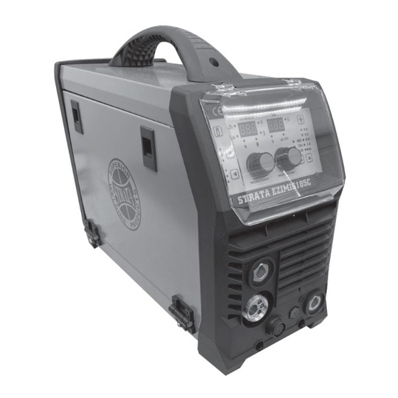
EZIMIG185C 2. OPERATION 2.1 Layout for the front and rear panel 1. MIG Torch Euro Connector 2. Negative (-) welding power output connection socket. 3. Positive (+) welding power output connection socket. 4. On/off switch 5. Gas inlet connector 6. Input power cable. - Page 7 EZIMIG185C 1. Gas Check Button Spot Weld Length 2. Process Selection Button - MIG/MMA/LIFT TIG Voltage Display 3. Trigger Mode Select Button Overload Indicator 4. Wire Speed / Welding Current Dial Power On Indicator 5. Welding Voltage Dial Current Display 6.
-
Page 8: Care & Maintenance
EZIMIG185C 3. CARE & MAINTENANCE 3.1 Keep your Welding Machine in Top Condition The EZIMIG185C does not require any special maintenance, however the user should take care of the machine as follows: 1. Regularly clean the ven la on slots 2. -
Page 9: General Guide To Welding
Traditionally, welding thin materials whilst avoiding “blow-through” can be tricky with the MMA process. This being said, however, welding thin materials with a Strata machine will be noticeably easier because the arc is so stable and the output can be very finely adjusted down to very low amps. - Page 10 EZIMIG185C 4.2.2 The MIG Process 4.2.2.1 Description The acronym MIG stands for Metal Inert Gas. Metal’ refers to the fact that the filler metal itself (the MIG wire) is used to conduct the welding current to the job and create the arc. Inert Gas refers to the fact that the process relies on an inert gas to prevent weld oxidisa on.
-
Page 11: Joint Preparations
EZIMIG185C 4.3 Joint Preparations In many cases, it will be possible to weld steel sec ons without any special prepara on. For heavier sec ons and for repair work on cas ngs, etc., it will be necessary to cut or grind an angle between the pieces being joined to ensure proper penetra on of the weld metal and to produce sound joints. - Page 12 EZIMIG185C Figure 33 Figure 34 Figure 36 Figure 35 www.strata.co.nz...
-
Page 13: Mig Basic Welding Guide
EZIMIG185C 5. MIG BASIC WELDING GUIDE 5.1 MIG Basic Welding Techniques Two different welding processes are covered in this sec on (GMAW and FCAW), with the inten on of providing the very basic concepts in MIG welding, where a welding torch is hand held, and the electrode (welding wire) is fed into a weld pool, and the arc is shielded by a gas (GMAW) or flux cored wire (FCAW). -
Page 14: Position Of Mig Torch
EZIMIG185C 5.4 Position of MIG Torch The angle of MIG torch to the weld has an effect on the width of the weld. The welding torch should be held at an angle to the weld joint. (See Secondary Adjustable Variables below). Hold the torch so that the welding seam is viewed at all mes. -
Page 15: Mig Welding (Gmaw) Variables
EZIMIG185C 5.7 MIG Welding (GMAW) Variables Most of the welding done by all processes is on carbon steel. The items below describe the welding variables in short-arc welding of 0.6mm to 6mm mild sheet or plate. The applied techniques and end results in the MIG process are controlled by these variables. - Page 16 EZIMIG185C 3. Nozzle Angle: This refers to the posi on of the welding torch in rela on to the joint. The transverse angle is usually one half the included angle between plates forming the joint. The longitudinal angle is the angle between the centre line of the welding torch and a line perpendicular to the axis of the weld.
-
Page 17: Establishing The Arc And Making Weld Beads
EZIMIG185C 5.8 Establishing the Arc and Making Weld Beads Before a emp ng to weld on a finished piece of work, it is recommended that prac ce welds be made on a sample metal of the same material as that of the finished piece. The easiest welding procedure for the beginner to experiment with MIG welding is the flat posi on. -
Page 18: Suggested Settings For Typical Mig Applications
EZIMIG185C 5.9.4 How to determine correct Wire Speed/Voltage Setting If the Current/Amperage (Wire Speed) is too high for the welding voltage, “stubbing” will occur as the wire dips into the molten pool and does not melt. Welding in these condi ons normally produces a poor weld due to lack of fusion. -
Page 19: Maintenance Of Mig Gun Mechanism
EZIMIG185C 5.12 MIG Torch /Spool Gun control 5.12.1 Parts Diagram for the MIG GUN 5.12.2 Binzel MT250 MIG Torch Range Parts MSS2557 Shroud Spring MSN2554 Swan Neck Assembly UG8015 Handle Cable Support C/W Ball Joint B2514 Ergo Handle Kit C/W Lock Nut... -
Page 20: Mig Welding Troubleshooting
EZIMIG185C 5.13 MIG Welding Troubleshooting The general approach to fix MIG welding problems is to start at the wire spool then work through to the MIG torch. There are two main areas where problems occur with MIG: Porosity and Inconsistent wire feed. - Page 21 EZIMIG185C 5.13.2 Wire Feed Problems TOP TIPS - Wire Jam Troubleshoo ng • If wire jam occurs when the torch becomes hot, this is o en because the heat causes the wire and the top to expand (which shrinks the hole in the p). Using a slightly oversize p can prevent this –...
- Page 22 EZIMIG185C 5.13.3 Weld Quality Problems Other weld problems can be reduced by checking the following points. Troubleshoo ng – MIG Weld Quality Fault Cause Remedy Undercut Welding arc voltage too high Decrease voltage or increase the wire feed speed. Incorrect torch angle Adjust angle.
- Page 23 EZIMIG185C Troubleshoo ng – MIG Weld Quality Fault Cause Remedy Cold weld puddle Loose welding cable connec on. Check welding cable connec ons Low power supply voltage. Contact supply authority Arc does not have a crisp The MIG torch has been connected...
-
Page 24: Stick (Mma) Basic Welding Guide
EZIMIG185C 6. STICK (MMA) BASIC WELDING GUIDE 6.1 Size of Electrodes The electrode size is determined by the thickness of metals being joined and can also be governed by the type of welding machine available. Small welding machines will only provide current (amperage) to run smaller sized electrodes. -
Page 25: Types Of Electrodes
EZIMIG185C 6.5 Types of Electrodes Arc Welding electrodes are classified into a number of groups depending on their applica ons. There are a great number of electrodes used for specialised industrial purposes which are not of par cular interest for everyday general work. -
Page 26: Mma Welding Techniques
EZIMIG185C 6.7 MMA Welding Techniques 6.7.1 A Word for Beginners For those who have not yet done any welding, the simplest way to commence is to run beads on a piece of scrap plate. Use mild steel plate about 6.0mm thick and a 3.2mm electrode. - Page 27 EZIMIG185C 6.7.4 Arc Length As soon as the arc is established, maintain a 1.6mm to 3.2mm gap between the burning electrode end and the parent metal. Draw the electrode slowly along as it melts down. The securing of an arc length necessary to produce a neat weld soon becomes almost automa c.
-
Page 28: Making Welded Joints
EZIMIG185C 6.8 Making Welded Joints Having a ained some skill in the handling of an electrode, you will be ready to go on to make up welded joints. 6.8.1 Making Welded Joints Set up two plates with their edges parallel, as shown in Figure 54, allowing 1.6mm to 2.4mm gap between them and tack weld at both ends. - Page 29 EZIMIG185C 6.8.2 Fillet Welds These are welds of approximately triangular cross-sec on made by deposi ng metal in the corner of two faces mee ng at right angles. Refer Figure 56 and Figure 57. A piece of angle iron is a suitable specimen with which to begin, or two lengths of strip steel may be tacked together at right angles.
- Page 30 EZIMIG185C 6.8.3 Vertical Welds 6.8.3.1 Vertical Up Tack weld a three feet length of angle iron to your work bench in an upright posi on. Use a 3.2mm of the job and strike the arc in the corner of the fillet. The electrode needs to be about 10º from the horizontal to enable a good bead to be deposited.
- Page 31 EZIMIG185C 6.8.4 Overhead Welds Apart from the rather awkward posi on necessary, overhead welding is not much more difficult that down hand welding. Set up a specimen for overhead welding by first tacking a length of angle iron at right angles to another piece of waste pipe. Then tack this to the work bench or hold in a vice so that the specimen is posi oned in the overhead posi on as shown in the sketch.
-
Page 32: Mma (Stick) Troubleshooting
EZIMIG185C 6.9 MMA (Stick) Troubleshooting Fault Cause Remedy A gap is le by failure of the Welding current too low. Increase welding current. weld metal to fill the root of Electrode too large for joint. smaller diameter the weld. electrode. - Page 33 EZIMIG185C Fault Cause Remedy Por ons of the weld run do Small electrodes used on heavy Use larger electrodes and not fuse to the surface of the cold plate. preheat the plate. metal or edge of the joint. Welding current is too low.
-
Page 34: Knowledge & Resources
1. Maintain labels and nameplates on the welder. These carry important informa on. If unreadable or missing, contact Strata for a replacement. 2. Avoid uninten onal star ng. Make sure the welder is setup correctly and you are prepared to begin work before turning on the welder. - Page 35 EZIMIG185C 5. Do not touch live electrical parts. Wear dry, insula ng gloves. Do not touch the electrode or the conductor tong with bare hands. Do not wear wet or damaged gloves. 6. Protect yourself from electric shock. Do not use the welder outdoors. Insulate yourself from the work piece and the ground.
-
Page 36: Welding Safety Instructions & Warnings
EZIMIG185C 8.4 Welding Safety Instructions & Warnings WARNING! Protect yourself and others from possible serious injury or death. Keep children away. Read the opera ng/Instruc on manual before installing, opera ng or servicing this equipment. Have all installa on, opera on, maintenance, and repair work performed by qualified people. - Page 37 EZIMIG185C 8.4.1 Personal Safety CAUTION! Keep the work area well lit. Make sure there is adequate space surrounding the work area. Always keep the work area free of obstruc ons, grease, oil, trash, and other debris. Do not use equipment in areas near flammable chemicals, dust, and vapours.
- Page 38 EZIMIG185C 8.4.4 Work Environment Safety DANGER! Remove any combus ble material from the work area. 1. When possible, move the work to a loca on well away from combus ble materials. If reloca on is not possible, protect the combus bles with a cover made of fire resistant material.
- Page 39 EZIMIG185C 5. Properly install and ground this equipment according to na onal, state, and local codes. 6. Turn off all equipment when not in use. Disconnect power to equipment if it will be le una ended or out of service.
-
Page 40: Maintenance & Troubleshooting
EZIMIG185C ▲In case of problems, contact your local dealer if no our authorized maintenance man. 9. MAINTENANCE & TROUBLESHOOTING 9.1 Maintenance In order to guarantee that arc welding machine works high-efficiently and in safety, it must be maintained regularly. Let customers understand the maintenance methods and means of arc... -
Page 41: Troubleshooting
EZIMIG185C Observe that Whether the current output cable is damaged. Ifitis damaged, it should be wrapped up, insulated or changed. Using the dry compressed air to clear the inside of arc welding machine. Especially for clearing up the dusts on radiator, main voltage transformer, inductance, IGBT module, the fast recover diode and PCB, etc. - Page 42 EZIMIG185C Troubles Reasons Solution Breakerdamaged Changeit Closethebreaker,butthe Fusedamaged Changeit powerlightisn’ton Powerdamaged Changeit Afterweldingmachineis Fandamaged Changeit over-heat,thefandoesn’t Thecableisloosen Screwthecabletightly work Nogasinthegascylinder Changeit Nooutput Gaspipeleaksgas Changeit Pressthe gaswhentest gunswitch, Electromagneticvalve Changeit nooutput damaged shieldedgas Controlswitchdamaged Repairtheswitch Outputgas whentestgas Controlcircuitdamaged Checktheboard Motordamaged Checkandchangeit Wirereel doesn’twork...
-
Page 43: Electrical Schematic Drawing
EZIMIG185C 9.3 Electrical schematic drawing www.strata.co.nz... -
Page 44: Warranty
EZIMIG185C Warranty As part of an on-going commitment to excellence in prod- Warranty does not cover pre delivery service and adjust- uct support, Euroquip offers a comprehensive product ment, or failure that may occur as a result of lack of/ incor- warranty program. - Page 45 EZIMIG185C www.strata.co.nz...
- Page 46 EZIMIG185C www.strata.co.nz...
- Page 47 EZIMIG185C www.strata.co.nz...
- Page 48 Congratulations on your new STRATA product. We are proud to have you as our customer and will strive to provide you with the best service and reliability in the industry. This product is backed by our extensive warranty. To locate your nearest distributor or service agency visit www.strata.co.nz, or email us at...
Need help?
Do you have a question about the EZIMIG185C and is the answer not in the manual?
Questions and answers