Table of Contents
Advertisement
Quick Links
TLE4241SYS_SHIELD
User guide
LITIX
Linear
™
Z8F80503016
About this document
Scope and purpose
The TLE4241GM is an AEC qualified adjustable current LITIX
embeds:
•
Built-in diagnosis and protection features
•
Adjustable constant output current up to 70 mA
•
Wide input voltage range
•
Voltage loop availability to implement constant output voltage power supply
The device also incorporates a PWM input that offers the possibility to adjust the LED brightness by pulse width
modulation.
The TLE4241SYS_SHIELD can be used for:
•
Standalone evaluation board for TLE4241GM device
•
Shield for Arduino
The board is especially suited to quickly setup demos in the context of blind spot indication as it features input
for ultrasound sensor, has an integrated buzzer and features 3 LEDs. Such designs are typically found in rear
radar applications or are directly integrated into mirrors.
Intended audience
The scope of this user guide is to provide instructions on the use of TLE4241SYS_SHIELD.
This user guide describes the TLE4241SYS_SHIELD with PCB version P02. Additionally, schematic version S02 is
described.
Evaluation board
This board is to be used during the design-in process for evaluation and proof of concepts for new projects
adopting the TLE4241GM.
Note:
PCB and auxiliary circuits are NOT optimized for final customer design.
User guide
Please read the sections "Important notice" and "Warnings" at the end of this document
www.infineon.com
Linear device, especially designed to drive LEDs. It
™
Rev.1.00
2023-10-23
Advertisement
Table of Contents

Related Manuals for Infineon TLE4241SYS SHIELD


Summary of Contents for Infineon TLE4241SYS SHIELD
-
Page 1: About This Document
This board is to be used during the design-in process for evaluation and proof of concepts for new projects adopting the TLE4241GM. Note: PCB and auxiliary circuits are NOT optimized for final customer design. User guide Please read the sections "Important notice" and "Warnings" at the end of this document Rev.1.00 www.infineon.com 2023-10-23... -
Page 2: Important Notice
Boards provided by Infineon Technologies. The design of the Evaluation Boards and Reference Boards has been tested by Infineon Technologies only as described in this document. The design is not qualified in terms of safety requirements, manufacturing and operation over the entire operating temperature range or lifetime. -
Page 3: Safety Precautions
TLE4241SYS_SHIELD User guide Safety precautions Safety precautions Safety precautions Note: Please note the following warnings regarding the hazards associated with development systems. Table 1 Safety precautions Warning: The evaluation or reference board contains DC bus capacitors which take time to discharge after removal of the main supply. -
Page 4: Table Of Contents
TLE4241SYS_SHIELD User guide Table of contents Table of contents About this document ..............1 Important notice . -
Page 5: The Board At A Glance
TLE4241SYS_SHIELD User guide 1 The board at a glance The board at a glance TLE4241GMSHIELD is an extension board for Arduino UNO intended to evaluate 2 main applications for automotive environment (please refer to Chapter 2.3): • Blind spot indicator •... -
Page 6: System And Functional Description
TLE4241SYS_SHIELD User guide 2 System and functional description System and functional description Getting started The jumpers are positioned as follows when TLE4241GMSHIELD is operating both in standalone condition or is connected to Arduino UNO. Table 2 Jumper position Jumper number Condition Description J_OL... -
Page 7: Description Of The Functional Blocks
Pin strip to close Button for scenario selection Connector for ultra sound sensor Figure 3 Button and connector for ultrasound sensor position Note: Example code is not provided in this user guide, and can be downloaded from Infineon website. User guide Rev.1.00 2023-10-23... -
Page 8: Blind Spot Indicator Function
TLE4241SYS_SHIELD User guide 2 System and functional description 2.3.1 Blind spot indicator function In general, blind spot detection system is designed to assist the driver by monitoring the blind spots on both sides of the vehicle. When blind spot indicator scenario is selected, by selecting on-board Scenario Selection S1 button on the board, the ultra sonic sensor detects any obstacle within 30 cm. -
Page 9: Fault Detection
TLE4241SYS_SHIELD User guide 3 Fault detection Fault detection The system has been designed to detect the following error conditions: • Open load • Short to GND • Overtemperature In each case, ST pin will be pulled LOW, and the error status will be detected to Arduino UNO board (if connected). -
Page 10: System Design
TLE4241SYS_SHIELD User guide 4 System design System design Schematics Figure 4 TLE4241GMSHIELD_S03_P03_schematic User guide Rev.1.00 2023-10-23... -
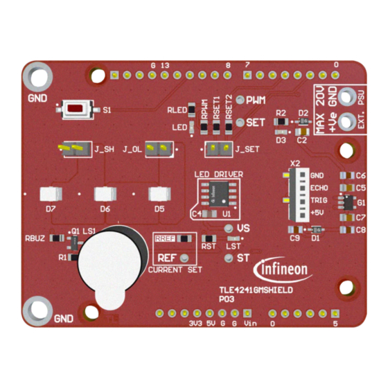
Page 11: Pcb Layout
TLE4241SYS_SHIELD User guide 4 System design PCB layout Figure 5 PCB layout top view Figure 6 PCB layout bottom view - flipped horizontally User guide Rev.1.00 2023-10-23... -
Page 12: Bill Of Material
100nF CAP / CERA / 100nF / 50V / 10% / X7R (EIA) / -55°C to 125°C / 805(2012) / SMD / - D1, D2 BAS3010A-03W Medium Power AF Schottky Diode Infineon Technologies Green Standard 0603 SMD LED Vishay D5, D6, D7 ... - Page 13 4 System design Quantity Designator Value Description Manufacturer PTS636 SK25F Tactile Switches With Home Automation And C&K SMTR LFS Remote Control, 12V TLE4241GM Adjustable Current LITIX Linear Infineon Technologies SSM-104-L-SV Tiger Claw Surface Mount Socket, 4Pin Samtec User guide Rev.1.00 2023-10-23...
-
Page 14: References
TLE4241SYS_SHIELD User guide References References Infineon TLE4241GM datasheet; https://www.infineon.com/cms/en/product/power/lighting-ics/litix- automotive-led-driver-ic/litix-linear/tle4241gm/#!documents User guide Rev.1.00 2023-10-23... -
Page 15: Revision History
TLE4241SYS_SHIELD User guide Revision history Revision history Document Date of Description of changes version release Rev.1.00 2023-10-23 • Initial document release User guide Rev.1.00 2023-10-23... -
Page 16: Disclaimer
Infineon Technologies, Email: erratum@infineon.com Infineon Technologies’ products may not be used in any applications where a failure of the product or any consequences of the use thereof can reasonably be Document reference expected to result in personal injury.
Need help?
Do you have a question about the TLE4241SYS SHIELD and is the answer not in the manual?
Questions and answers