Table of Contents
Advertisement
Quick Links
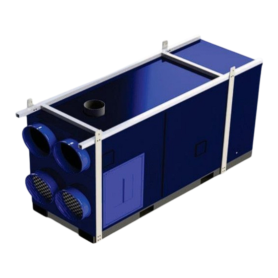
OIL - FIRED CONSTRUCTION HEATER
Installation - Operation Maintenance
READ INSTRUCTIONS PRIOR TO STARTING HEATERS
FROST FIGHTER INC.
125 FURNITURE PARK
WINNIPEG, MANITOBA
CANADA R2G 1B9
TEL: (204) 775-8252
FAX: (204) 783-6794
WWW.FROST-FIGHTER.COM
Instructions and Parts List
1-888-792-0374
MODEL
IHS 700
JULY 2008 TO
PRESENT
MAY 2024
Advertisement
Table of Contents

Related Manuals for Frost Fighter IHS 700


Summary of Contents for Frost Fighter IHS 700
- Page 1 OIL - FIRED CONSTRUCTION HEATER MODEL IHS 700 JULY 2008 TO PRESENT Installation - Operation Maintenance Instructions and Parts List READ INSTRUCTIONS PRIOR TO STARTING HEATERS FROST FIGHTER INC. 125 FURNITURE PARK WINNIPEG, MANITOBA CANADA R2G 1B9 TEL: (204) 775-8252 FAX: (204) 783-6794 WWW.FROST-FIGHTER.COM...
- Page 2 IMPORTANT INSTRUCTIONS 1. READ ALL INSTRUCTIONS BEFORE INSTALLING OR USING THIS HEATER. 2. This heater is hot when in use. To avoid burns do not touch hot surfaces. Keep combustible materials such as furniture, papers, clothes, curtains, tarps, plastic sheets, combustible building materials &...
-
Page 3: Table Of Contents
PAGE 17 SEQUENCE OF OPERATION PAGE 18 SEQUENCE OF OPERATION FOR GENISYS CONTROLLER PAGE 19-20 TROUBLE SHOOTING GUIDE PAGE 21 IHS 700 WIRING PANEL PAGE 22-24 REPLACEMENT PARTS FOR BURNER PAGE 25-26 TIGERLOOP SYSTEM PAGE 27 IHS-700 OIL WIRING SCHEMATIC... -
Page 4: Safety Information And Safety Instructions
SAFETY INFORMATION AND SAFETY INSTRUCTIONS STANDARD WARNING SYMBOLS INDICATES EXTREME HAZARD THAT COULD RESULT IN INJURY OR DEATH INDICATES POSSIBLE HAZARD THAT COULD DAMAGE EQUIPMENT OR PROPERTY AND/OR RESULT IN INJURY INDICATES POSSIBLE HAZARD THAT COULD CAUSE IMPROPER OPERATION OR DAMAGE EQUIPMENT OTHER SPECIFIC HAZARD SYMBOLS THESE SYMBOLS ARE USED THROUGHOUT THIS MANUAL TO INDICATE SPECIFIC HAZARDS RISK OF FIRE OR EXPLOSION... - Page 5 INSTALLATION- OPERATION MAINTENANCE INSTRUCTIONS READ INSTRUCTIONS PRIOR TO OPERATING HEATER GENERAL HAZARD WARNING FAILURE TO COMPLY WITH PRECAUTIONS AND INSTRUCTIONS PROVIDED WITH THIS HEATER CAN RESULT IN DEATH, SERIOUS BODILY INJURY AND PROPERTY LOSS OR DAMAGE FROM HAZARDS OF FIRE, EXPLOSION, BURN ASPHYXIATION, CARBON MONOXIDE POISONING, AND/OR ELECTRICAL SHOCK.
- Page 6 OPERATORS RESPONSIBILITY Installation and adjustment of the burner requires technical knowledge and the use of combustion test instruments. Do not tamper with the unit or any safety controls. Call your qualified service technician. Incorrect operation of the burner could result in severe personal injury, death, or substantial property damage.
-
Page 7: Specifications
SPECIFICATIONS MODEL IHS-700 FUEL TYPES #1 or #2 Fuel Oil / Diesel Fuel 4.00 USGPH NOZZLE 45’ B (SOLID) SIZE PUMP 140 P.S.I.g * PRESSURE Band: AIR SETTING Shutter: Burner Slide Plate Setting: 4.5 APPROVAL AGENCY * Pressure at the bleeder port. Subtract 10 PSI if measured at the pump discharge port. -
Page 8: Pre-Installation Checklist
PRE-INSTALLATION CHECKLIST COMBUSTION AIR SUPPLY The burner requires combustion air and ventilation air for reliable operation. Assure that the Building and/or combustion air openings comply with National Fuel Gas Code NFPA 54/CSA B149. For appliance/burner units in confined spaces, the room must have an air opening near the top of the room plus one near the floor, each with a free area at least one square inch per 1000 Btu/hr input of all fuel burning equipment in the room. -
Page 9: Vent System
VENT SYSTEM The flue gas venting system must be in good condition and must comply with all the applicable codes. OUTDOOR INSTALLATIONS: For outdoor installation, a vent cap must be installed and fastened. INDOOR INSTALLATIONS: Must be done in accordance to NFPA 54 (or CSA B139) with local authorities having jurisdictions. 1. -
Page 10: Horizontally Vented Units
90 Degree elbow Straight section Vent Diameter: 12"` Material: Single wall steel pipe or type A vent IHS 700 Vent installations shall conform with local codes, or, in the absence of local codes, with the National Fire Protection Standard for Oil-Burning Equipment,... -
Page 11: Electrical Supply
ELECTRICAL SUPPLY Verify that the power connections available are correct for the Unit. All power must be supplied through the disconnect. INSTALLING THE OPTIONAL THERMOSTAT Plug the thermostat directly into the receptacle. WARNING: THE RECEPTACLE IS ONLY USED FOR INSTALLING THE THERMOSTAT! THIS IS NOT A POWER SOURCE. CONNECT THE FUEL LINE(S) - REFER TO CHART BELOW FOR FUEL LINE LENGTH Install the oil lines using the following guidelines. - Page 12 140-300 psig SEQUENCE OF OPERATION – TYPICAL 1. Turn the unit switch to manual. 2. Power is applied to the Genisys black (BK) and red (RD) wires. 3. After 5 seconds, the Genisys applies 120 volts to the orange wire (OR), activating the burner motor (M1) and the ignition transformer (TR).
-
Page 13: Preparing The Burner For Start-Up
PUMP PRESSURE The pump pressure is 150 PSI for the IHS 600 and 140 PSI for the IHS 700. The pump pressure is adjusted on the side of the pump. (See page 8 Two-pipe oil flow) - Page 14 AIR SETTING The air settings should be set to 6 on the band and 8 on the air shutter. In some cases, these air-settings need to be adjusted. To do this insert your flue gas analyzer into the flue, 6 inches above the top of unit. Measure you excess O2% and CO2% levels. Set your air shutter to bring your O2% levels between 4-5%.
-
Page 15: Maintenance And Service
MAINTENANCE AND SERVICE Operation and adjustment of the burner requires technical knowledge and the use of combustion test instruments. Do not tamper with the burner or controls. Failure to comply could result in failure or the burner or system, resulting in severe personal injury, death, or substantial property damage. -
Page 16: Install Nozzle
INSTALL NOZZLE Install the oil nozzle in the nozzle adaptor. Use a ¾” open-end wrench to steady the nozzle adaptor and use a 5/8” open-end wrench to turn the nozzle. Tighten securely but do not overtighten. Verify that the oil tube assembly and electrodes are in good condition, with no cracks or damage. Failure to properly set and maintain the electrode and nozzle spacing dimensions can cause incorrect burner ignition or poor combustion. -
Page 17: Bearing Installation And Maintenance
BEARING INSTALLATION AND MAINTENANCE NOTE: To prevent premature failure – please ensure greasing instructions below are applied. As well, tighten bearing set screws, collars, and wheel lugs every four to six months. ENGINEERING – BALL & ROLLER BEARINGS LUBRICATION For bearings that are equipped with a hydraulic grease fitting threaded into the housing for ease of lubrication, the proper amount of lubricant in the bearing is important. - Page 18 TABLE I. RECOMMENDED LUBRICATION Ball Bearings Roller Bearings Shaft Size Grease Charge Shaft Size Grease Charge (inches) (ounces) (inches) (ounces) 1 – 1 ½ 1 – ½ to 1 – 1 1/16 0.15 0.32 Frequency of re-lubrication depends upon operating conditions. The bearing operating temperature is the best index for determining a re-lubrication schedule.
-
Page 19: Tensioning V-Belt Drives
TENSIONING V-BELT DRIVES 1. Ideal tension is the lowest tension at which the belt will not slip under peak load conditions. 2. Check tension frequently during the first 24-48 hours of operation. 3. Over-tensioning shortens the belt and bearing life. 4. -
Page 20: Sequence Of Operation
SEQUENCE OF OPERATION 1. SYSTEM SWITCH “MANUAL” After a forty-five second purge period, the burner fires. Thirty seconds after the burner fires the supply fan starts. 2. SYSTEM SWITCH “THERMOSTAT” (the Heat Switch is inoperative in this mode) On a call for heat from the thermostat, after a forty-five second purge period, the burner fires. Thirty seconds after the burner fires the supply fan starts. -
Page 21: Sequence Of Operation For Genisys Controller
Sequence of Operation for Genisys Controller urner States Standby: The burner is idle, waiting for a call for heat. Valve-On Delay: The igniter and motor are on while the control delays turning on the oil solenoid valve for 45 seconds. Trial For Ignition: The oil solenoid valve is energized. -
Page 22: Trouble Shooting Guide
TROUBLE SHOOTING GUIDE ALWAYS DOUBLE CHECK FOR SUFFICIENT POWER, GAUGE OF CORD (SEE TOP OF PAGE #5) AND PROPER FUEL SUPPLY. POWER AND FUEL SUPPLY MUST BE SHUT OFF/DISCONNECTED BEFORE REMOVING OR REPLACING ANY COMPONENTS ON THE HEATER. Unit is turned on; nothing happens after 5 second safe start. a. - Page 23 TROUBLE SHOOTING GUIDE d. Wires between cad cell and primary control should be checked to see that they are not pinched or crimped.. e. Prime fuel pump by loosening bleeder screw till steady stream of fuel comes out to ensure no air or bubbles in fuel line. If unit locks out three times in succession, it will go into restricted lock out mode.
-
Page 24: Ihs 700 Wiring Panel
IHS 700 Wiring Panel... - Page 25 REPLACEMENT PARTS...
- Page 26 REPLACEMENT PARTS...
- Page 27 B48254 AIR SHUTTER 48139 SUNTEC "A" OIL PUMP 2591U 48152 8" OIL DELIVERLY TUBE 5394 B48264 HEAD ASSEMBLY B70262 ELECTRODES IHS 700 OIL B60256 6" AIR TUBE COMBO FOR CF800 48140 1/3 HP BURNER MOTOR B30141A BLOWER WHEEL - 21339U...
- Page 28 48011 Tigerloop Single Line Remote Kit w/Filter...
- Page 29 SAFETY OIL SUPPLY SYSTEM FOR REMOTE FUEL CELL...
-
Page 30: Ihs-700 Oil Wiring Schematic
IHS-700 OIL WIRING SCHEMATIC... -
Page 31: Frostfighter Warranty
6. The heating elements and controls show no sign of overheating or operation in conditions with corrosive or abrasive dusts or gasses. No representative of Frost Fighter Inc., nor any of its distributors or dealers, is authorized to assume for Frost Fighter Inc. any other obligations or liability in connection with this product, nor alter the terms of the warranty in any way.
Need help?
Do you have a question about the IHS 700 and is the answer not in the manual?
Questions and answers