Table of Contents
Advertisement
Quick Links
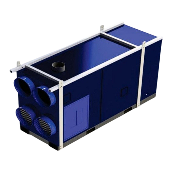
GAS - FIRED CONSTRUCTION HEATER
PROPANE AND NATURAL GAS
Installation – Operation/Maintenance Instructions
READ INSTRUCTIONS PRIOR TO STARTING HEATERS
FROST FIGHTER INC.
125 FURNITURE PARK
WINNIPEG, MANITOBA
CANADA R2G 1B9
TEL: (204) 775-8252
FAX: (204) 783-6794
and Parts List
WWW.FROST-FIGHTER.COM
1-888-792-0374
MODEL
IHS 700
JULY 2008 TO
PRESENT
REV 1.2.0
MAY 2024
Advertisement
Table of Contents

Subscribe to Our Youtube Channel
Related Manuals for Frost Fighter IHS 700


Summary of Contents for Frost Fighter IHS 700
- Page 1 GAS - FIRED CONSTRUCTION HEATER PROPANE AND NATURAL GAS MODEL IHS 700 JULY 2008 TO PRESENT Installation – Operation/Maintenance Instructions and Parts List READ INSTRUCTIONS PRIOR TO STARTING HEATERS FROST FIGHTER INC. 125 FURNITURE PARK WINNIPEG, MANITOBA CANADA R2G 1B9...
- Page 2 IMPORTANT INSTRUCTIONS 1. READ ALL INSTRUCTIONS BEFORE INSTALLING OR USING THIS HEATER. 2. This heater is hot when in use. To avoid burns do not touch hot surfaces. Keep combustible materials such as furniture, papers, clothes, curtains, tarps, plastic sheets, combustible building materials &...
-
Page 3: Table Of Contents
IHS 700 LP/NG PAGE 1-3 SAFETY INFORMATION AND SAFETY INSTRUCTIONS PAGE 4 GENERAL NOTES, ELECTRICAL NOTES, ADDITIONAL INSTRUCTIONS PAGE 4-5 LIGHTING INSTRUCTIONS IHS 700 (LPNG) PAGE 6 INSTALLATION INSTRUCTIONS PAGE 7 GAS LEAKAGE TESTING, PRE-INSTALLATION CHECKLIST PAGE 8 VENT SYSTEM... -
Page 4: Safety Information And Safety Instructions
SAFETY INFORMATION AND SAFETY INSTRUCTIONS STANDARD WARNING SYMBOLS INDICATES EXTREME HAZARD THAT COULD RESULT IN INJURY OR DEATH INDICATES POSSIBLE HAZARD THAT COULD DAMAGE EQUIPMENT OR PROPERTY AND/OR RESULT IN INJURY INDICATES POSSIBLE HAZARD THAT COULD CAUSE IMPROPER OPERATION OR DAMAGE OTHER SPECIFIC HAZARD SYMBOLS THESE SYMBOLS ARE USED THROUGHOUT THIS MANUAL TO INDICATE SPECIFIC HAZARDS RISK OF FIRE OR EXPLOSION... - Page 5 INSTALLATION- OPERATION MAINTENANCE INSTRUCTIONS READ INSTRUCTIONS PRIOR TO OPERATING HEATER GENERAL HAZARD WARNING FAILURE TO COMPLY WITH PRECAUTIONS AND INSTRUCTIONS PROVIDED WITH THIS HEATER CAN RESULT IN DEATH, SERIOUS BODILY INJURY AND PROPERTY LOSS OR DAMAGE FROM HAZARDS OF FIRE, EXPLOSION, BURN ASPHYXIATION, CARBON MONOXIDE POISONING, AND/OR ELECTRICAL SHOCK.
- Page 6 OPERATORS RESPONSIBILITY Installation and adjustment of the burner requires technical knowledge and the use of combustion test instruments. Do not tamper with the unit or any safety controls. Call your qualified service technician. Incorrect operation of the burner could result in severe personal injury, death, or substantial property damage.
-
Page 7: Lighting Instructions Ihs 700 (Lpng)
CAN/CSA 3.2. The intended use is for 5, the temporary heating of building or structures under construction, alteration, or repair. 2. Frost Fighter cannot anticipate every use, which may be made of our heaters. CHECK WITH YOUR LOCAL FIRE AND SAFETY AUTHORITY IF YOU HAVE QUESTIONS ABOUT SAFE APPLICATIONS. - Page 8 CONNECTING THE PROPANE TANK 1. The gas connection on the heater is 1” NPT. Ensure you have the proper fittings to connect to the heater. 2. The maximum supply pressure to the heater is 14” W.C. (1/2 PISG). 3. Ensure the proper regulators are installed to reduce the tank pressure to 14” W.C. maximum 11”...
-
Page 9: Installation Instructions
INSTALLATION INSTRUCTIONS: 1. The installation shall conform with local codes, or, in the absence of local codes, with the National Fuel Gas Code, ANSI Z223.1/NFPA 54, or the National Gas and Propane Installation Code, CSA B149.1. 2. Inspect the heater before each use and have it annually inspected by a qualified agency. 3. - Page 10 GAS LEAKAGE TESTING After removal for service or replacing components on the gas manifold a gas leakage test must be performed. Close main gas firing valve on the gas manifold. Connect your source gas to the gas manifold. Once connections are tightened, open-source gas, fire unit. On each connection and fitting, apply soap solution and check for bubbles.
-
Page 11: Vent System
VENT SYSTEM The flue gas venting system must be in good condition and must comply with all the applicable codes. The IHS 700 is a category III appliance. OUTDOOR INSTALLATIONS: For outdoor installation a vent cap must be installed and fastened. -
Page 12: Horizontal Flue Venting
Straight section Vent Diameter: 8" Material: Single wall steel pipe or type A vent IHS 700 Vent installations shall conform with local codes, or, in the absence of local codes, with the National Fuel Gas Code, ANSI Z223.1/NFPA 54, or the National Gas and Propane installation Code, CSA B149.1... - Page 13 ELECTRICAL SUPPLY Verify that the power connections available are correct for the Unit. All power must be supplied through the disconnect. INSTALLING THE OPTIONAL THERMOSTAT Plug the thermostat directly into the receptacle. WARNING: THE RECEPTACLE IS ONLY USED FOR INSTALLING THE THERMOSTAT! THIS IS NOT A POWER SOURCE. PREPARE THE BURNER FOR START-UP Start-up checklist –...
- Page 14 MAINTENANCE AND SERVICE cont. Additionally, you should have the burner checked as indicated below, by your local authorized dealer. Check burner distributor head and mixing plates. Clean if necessary. Check ignition electrode. Clean, adjust or replace as necessary. Check the flame sensor rod (ionization rod) for dirt or carbon build up. Clean, adjust, or replace as necessary.
-
Page 15: Electrode And Flame Probe Adjustments
ELECTRODE AND FLAME PROBE ADJUSTMENTS 5/16" Do not turn the ignition electrode. Leave it as shown in the drawing. If the ignition electrode is put near the ionization probe, the amplifier control box may be damaged. -
Page 16: Bearing Installation And Maintenance
BEARING INSTALLATION AND MAINTENANCE NOTE: To prevent premature failure – please ensure greasing instructions below are applied. As well, tighten bearing set screws, collars, and wheel lugs every four to six months. ENGINEERING – BALL & ROLLER BEARINGS LUBRICATION For bearings that are equipped with a hydraulic grease fitting threaded into the housing for ease of lubrication, the proper amount of lubricant in the bearing is important. - Page 17 TABLE I. RECOMMENDED LUBRICATION Ball Bearings Roller Bearings Shaft Size Grease Charge Shaft Size Grease Charge (inches) (ounces) (inches) (ounces) 1 – 1 ½ 1 – ½ to 1 – 1 1/16 0.15 0.32 Frequency of re-lubrication depends upon operating conditions. The bearing operating temperature is the best index for determining a re-lubrication schedule.
-
Page 18: Tension V-Belt Drives
TENSIONING V-BELT DRIVES 1. Ideal tension is the lowest tension at which the belt will not slip under peak load conditions. 2. Check tension frequently during the first 24-48 hours of operation. 3. Over-tensioning shortens the belt and bearing life. 4. -
Page 19: Trouble Shooting Guide
TROUBLE SHOOTING GUIDE The equipment has been electrically, and fire tested prior to shipment. However, during transit, mis adjustment of controls and loose wires could develop. Do not assume a control is defective until it and its associated wiring is checked. This equipment has many items supplied to us by outside vendors. - Page 20 BURNER STARTING DIFFICULTIES AND THEIR CAUSES: 1. The burner goes to lockout after the prepurge period because the flame does not ignite. a. Air has not been fully evacuated from the gas lines. b. The gas valve is passing too little gas. c.
-
Page 21: Resetting The Control Box And Using Diagnostics
RESETTING THE CONTROL BOX AND USING DIAGNOSTICS The control box features a diagnostics function through which any causes of malfunctioning are easily identified (indicator: RED LED). To use this function, you must wait at least 10 seconds once it has entered the safety condition (lock-out), and then press the reset button. - Page 22 RESETTING THE CONTROL BOX AND USING DIAGNOSTICS cont. The sequence of pulses issued by the control box identifies the possible types of malfunction, which are listed in the table below. SIGNAL PROBABLE CAUSE The flame does not stabilise at the end of the safety time : 2 pulses -faulty ionization probe;...
-
Page 23: Exploded View Of Spare Parts
EXPLODED SPARE PARTS... -
Page 24: Ihs 700 Wiring Panel
IHS 700 Wiring Panel... -
Page 25: Ihs 700 Manifolds
Manifolds IHS 700 1 1" shut off ball valve - 70034 2 1" Conversion valve - 70034A 3 Dungs shut off solenoid - 70275 4 Low pressure gas switch - 70058 5 Asco shut off solenoid - 70274 6 Maxitrol 1/2 psig regulator - 700931... -
Page 26: Ihs 700 Lpng Wiring Schematic
IHS-700 LPNG WIRING SCHEMATIC... -
Page 27: Frostfighter Warranty
6. The heating elements and controls show no sign of overheating or operation in conditions with corrosive or abrasive dusts or gasses. No representative of Frost Fighter Inc., nor any of its distributors or dealers, is authorized to assume for Frost Fighter Inc. any other obligations or liability in connection with this product, nor alter the terms of the warranty in any way.
Need help?
Do you have a question about the IHS 700 and is the answer not in the manual?
Questions and answers