Table of Contents
Advertisement
Quick Links
Advertisement
Table of Contents

Subscribe to Our Youtube Channel
Related Manuals for Frost Fighter IDF1000


Summary of Contents for Frost Fighter IDF1000
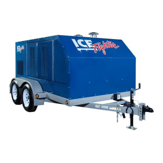
- Page 1 IDF1000 FEATURES AND OPERATION MANUAL VER. 1.3.4 Feb. 2018...
- Page 2 Table of Contents Page 2 Fuel Fill Location & Filling Precautions Page 3-4 Door latches, Compartments and Hitch/Tongue Details Page 5 External Power Connections Page 6-8 Heater Access Doors and Slide Out System Page 9 Basic Features of Heaters (See heater manual for full operating & servicing information) Page 10 Engine/Generator Layout and Identification (See engine manual for engine type specific detailed information)
-
Page 3: Fuel Fill Points
40 US (150 L)Gal.for generator tank Refer to rating plate in generator compartment for specific details. Approximate maximum run time for IDF1000 is approx. 32 hours. CAUTION: Do not attempt to fill tanks too quickly or overfill tanks which can increase the risk of spills or backsplash... -
Page 4: Positive Lock Access Door Latches
Page 3 Positive Lock Access Door Latches Door Latches in Closed Position Press Bottom of Latches to Open... - Page 5 Page 4 Trailer tongue area illustrating various components Left front storage compartment access door. Always ensure tow vehicle has sufficient tow ratings and reduce speed when towing Break-away switch battery. Check battery condition annually 7 Pin trailer connector to vehicle for exterior lights and Tongue jack electric brakes...
-
Page 6: External Power Connections
Page 5 External Power Connections • 120VAC 15A "shore power" inlet to supply engine block heater • 120VAC 15A GFCI protected auxiliary power and battery maintainer. outlet... -
Page 7: Swing Open Side Access Doors
Page 6 Swing Open Side Access Doors Access to Heater Discharges Access to Heater Controls Catches are provided Heater discharge doors have safety interlock switches to secure doors in the Heater inlet doors provide access to the heater controls and each door must be open in order for the respective open position and should normally remain open during operation. - Page 8 Page 7 Heaters are mounted onto poly lined slides rails permitting slide out access or complete removal from enclosure Illustration of Bolts securing slide rails in locked position...
- Page 9 Page 8 Illustration of a heater pulled into access positions. Heater travel is limited by a stop bolt but can be completely removed from the enclosure by unfastening the slide limit safety stop bolt. Note: IDH models allow for slide-out from the burner side of the trailer only...
-
Page 10: Idf500Hs Heaters
Page 9 IDF500HS Heaters Burner Controls and Functions See heater manual for complete operation and maintenance information PRESSURE GAUGE KEEP VALVE CLOSED DURING NORMAL OPERATION & OPEN TO ONLY TO CHECK PRESSURE. GENISYSY 7505 CONTROL BURNER CIRCUIT BREAKER IGNITION FUEL FILTER TRANSFORMER BURNER OPERATION SELECTOR SWITCH. -
Page 11: Diesel Generator
Page 10 Diesel Generator KUBOTA ENGINE UNIT ISUZU ENGINE UNIT Refer to Engine Manual for Instructions and Servicing Refer to Engine Manual for Instructions and Servicing... -
Page 12: Rear Compartment Power Distribution And Controls
Rear Compartment Power Distribution and Controls Page 11 Control functions for both Kubota & Isuzu engine versions are similar except that the fuel gauges & gauge lights are activated by the “Generator Lights” pushbutton on KUBOTA powered units and by the key-switch on the LOFA control turned to “Run” for ISUZU powered units. - Page 13 Page 12 Pushbuttons for Compartment Lighting and Accessories Momentary pushbuttons to activate time delay compartment Battery charger and block heater switches are push on - push off lighting. switches with indicator lights. (and fuel gauges on Kubota powered units) These are functional whenever the unit is connected to a shore 120VAC power source.
- Page 14 Fuel Level Sending Units Page 13 0-180 ohm. Heater Tank 33-240 ohm. Generator Tank Fuel Level Sender Fuel Level Senders...
- Page 15 Page 14 Compartment Lighting Timers • Compartment lighting (and fuel gauge operation on Kubota powered units) is controlled with time-delay controls activated with momentary pushbutton controls on the panel to prevent battery drain from constant unattended operation. • The operation and timing functions can be adjusted if needed. •...
- Page 16 Page 15 Gaining Access to Timing Modules and Low Voltage Fuses ISUZU POWERED UNITS REMOVE THE FRONT KUBOTA UNITS REMOVE THE TOP SIDE BOLTS AND PANEL BOLTS AND LIFT THE FRONT COVER TO THE FRONT OF THE PANEL WILL HINGE DOWN. ACCESS THE TIMERS Fuses for 12VDC Power are located inside control panel...
- Page 17 Page 16 • 7 Different Settable Timing Period Ranges 0.1 sec. to 1 sec. • 1 sec. to 10 sec. • 6 sec. to 60 sec. • 1 min. to 10 min.* • 6 min. to 60 min. • 1 hr. to 10 hr. •...
- Page 18 Page 17 • Timing period within the selected range can be adjusted by turning the black dial and using 0 to 10 scale • In the factory setting 1 min. to 10 min. range each number on the scale represents 1 min.
- Page 19 Page 18 Starting the Kubota Engine Turn key-switch to “PREHEAT” position and press and hold the Turn key-switch to “START” position while continuing to hold the Murphy Switch (safety override) to begin fuel pump. Murphy Switch in until the engine starts and release key-switch back to “RUN”...
-
Page 20: Starting The Isuzu Engine
Page 19 Starting the Isuzu Engine Turn key-switch on LOFA control from Preheating will be shown by When“PREHEAT” indicator light goes illuminated “PREHEAT” off move key-switch to "START" and “OFF” to “RUN” position. indicator light. release once engine starts.. LOFA control with key-switch placed in “RUN” position is also To stop engine move key-switch to the used to activate fuel gauges &... - Page 21 Page 20 ISUZU MOTORS AMERICA, LLC MODEL 3CH1NGZG1 ISZJ SPEC NO. IS-15-098-0 PowerTrain Division B3-19E46-0020, N/A DWG NO./DATE BASIC ENGINE 1.3L, 3 CYL, 4 STROKE, WTR COOLED, OHV, I/L, INDIRECT INJECTED, NATURALLY DESCRIPTION ASPIRATED DIESEL B:80mm, S:84mm, CR:23.1:1, GLOW PLUG ASSISTED START ENGINE INDUSTRIAL F/F GENSET ENGINE 14.3 BHP@1800 RPM (STANDBY)
- Page 22 Baldwin PA3476 / LUBERFINER LAF8823 / WIX 49410 Air Cleaner Element 15741-11080 (WA10015 Outer) Valve Cover gasket 1G700-14520 Alternator 16231-64012 Starter 6A230-59210 Thermostat 19434-73014 Thermostat Gasket 16221-73270 Water Pump 16251-73034 Water Pump Gasket 16239-74014 Fan Belt 16282-97013 Stop Solenoid 17208-60016 Frost Fighter Jan. 2015...
-
Page 23: Important Warnings And Precautions
Page 22 IMPORTANT WARNINGS AND PRECAUTIONS Rating Plate Information and Serial Number Located UNDERSTAND AND OBSERVE ALL RULES AND PRECAUTIONS REGARDING THE on inside wall of Generator/Control Compart ment TOWING OF A TRAILER & USE AN APPROPRIATELY RATED AND EQUIPPED TOW VEHICLE ENSURE THAT ALL MINIMUM CLEARANCES STATED ON THE RATING PLATE ARE MAINTAINED DURING OPERATION... - Page 24 X.XX .02 Draft Angle 3 Fractions 1/32 +12V UNITS DESIGNED X.XXX .005 Radius 1/8 .005 Tir +12V ENGINE CNTRL .001/Inch .002/Inch DATE 30-OCT-15 .001/Inch .001/Inch BATTERY BATTERY ACC. SIZE PART # REV. .001/Inch .001/Inch SCALE IDF1000 / 1DH1000 SURFACE FINISH 125...
- Page 25 AOJUSTABL£ TIME DELAY RELAY SEND 0 - 180 OHMS 1, 2 SEND 33 - 240 OHMS 12V CIRCUIT DIAGRAM FOR KUBOTA POWERED UNITS DRAWN BY ISSUED BY SCALE DRW. NO. IDF1000 IDH1000 CHK. BY DATE JOB NO. JUNE 19 15...
- Page 26 Page 25 AC GENERATOR GROUND 120 VAC BU< GROUND BU< HEATER 2 120VAC 20A GROUND EXTERIOR 120VAC 15A GFCI OUTlfT ----ci---:.B � I.A � C K ___________ � SWITCH 3 GROUND BATTERY BLOCK CHARGER HEATER Al & A2 - 120VAC 15A DUPLEX SPLIT RECEPT. AT REAR OF CONTROL PANEL TITLE TRAILER - GENERATOR 2 - IDF 500 HEATERS...
- Page 27 Approx. weight w/ full fuel - 6380 lbs. (2900 kg.) DRAWING IS THE SOLE PROPERTY OF FROST FIGHTER. ANY REPRODUCTION DIMENSIONS ARE IN MODEL: IDF1000 / IDH1000 IN PART OR AS A WHOLE WITHOUT THE INCHES TOLERANCES: FILENAME: N/A WRITTEN PERMISSION OF...
Need help?
Do you have a question about the IDF1000 and is the answer not in the manual?
Questions and answers