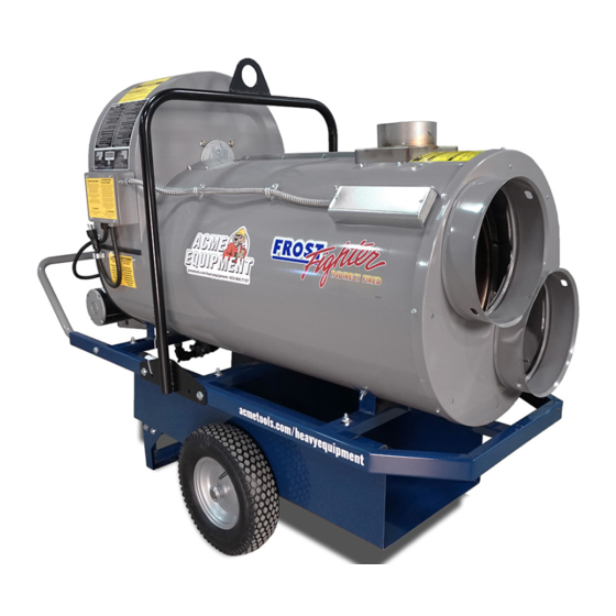
Frost Fighter IDH500QR LP/NG Installation - Operation/Maintenance Instructions And Parts List
Indirect fired space heaters propane and natural gas
Hide thumbs
Also See for IDH500QR LP/NG:
Table of Contents
Advertisement
Quick Links
INDIRECT FIRED SPACE HEATERS
PROPANE AND NATURAL GAS
Installation - Operation Maintenance
Instructions and Parts List
READ INSTRUCTIONS PRIOR TO STARTING HEATERS
FROST FIGHTER INC.
100-1500 NOTRE DAME AVE
WINNIPEG, MANITOBA
CANADA R3E 0P9
TEL : (204) 775-8252
FAX: (204) 783-6794
WWW.FROST-FIGHTER.COM
MODEL IDH500QR LP/NG
MODEL IDH350QR LP/NG
1-888-792-0374
Rev. 1.3
JUN. 2018
Advertisement
Table of Contents

Related Manuals for Frost Fighter IDH500QR LP/NG


Summary of Contents for Frost Fighter IDH500QR LP/NG
- Page 1 INDIRECT FIRED SPACE HEATERS PROPANE AND NATURAL GAS MODEL IDH500QR LP/NG MODEL IDH350QR LP/NG Installation - Operation Maintenance Instructions and Parts List READ INSTRUCTIONS PRIOR TO STARTING HEATERS FROST FIGHTER INC. 100-1500 NOTRE DAME AVE WINNIPEG, MANITOBA CANADA R3E 0P9...
- Page 2 FROSTFIGHTER WARRANTY Frostfighter Inc. warrants this heater free from defects in workmanship and materials for a period of twelve (12) months from the date of initial service not to exceed fifteen (15) months from date of shipment If during the warranty period, the heat exchanger fails under normal use and service due to a defect in material or workmanship said heat exchanger will be repaired or replaced free of charge F.O.B.
-
Page 3: For Your Safety
INSTALLATION- OPERATION MAINTENANCE INSTRUCTIONS READ INSTRUCTIONS PRIOR TO OPERATING HEATER GENERAL HAZARD WARNING FAILURE TO COMPLY WITH PRECAUTIONS AND INSTRUCTIONS PROVIDED WITH THIS HEATER CAN RESULT IN DEATH, SERIOUS BODILY INJURY AND PROPERTY LOSS OR DAMAGE FROM HAZARDS OF FIRE, EXPLOSION, BURN, ASPHYXIATION, CARBON MONOXIDE POISONING, AND/OR ELECTRICAL SHOCK. - Page 4 GENERAL NOTES: 1. The heater is designed and approved for use as a construction heater under ANSI Z83.7 with the applicable requirements of UL 795 and under CGA 2.14 with applicable requirements of CAN/CSA 3.2. The intended use is for 5 the temporary heating of building or structures under construction, alteration or repair.
- Page 5 MODELS AND SPECIFACTIONS MODEL IDH350QR LP/NG IDH500QR LP/NG HEATING CAPACITY 350,000 BTU 420,000 BTU NATURAL GAS/ NATURAL GAS/ FUEL PROPANE PROPANE CAPACITY POWER 115 VOLT 20 AMP 115 VOLT 20 AMP REQUIREMENTS BURNER MOTOR 1/4 HP 3450 RPM 1/4 HP 3450 RPM...
-
Page 6: Flue Pipe Connection
INSTALLATION CLEARANCES Top -3 inches (0.076 meters) Discharge End -10 f eet (3.05 meters) Sides -24 inches (0.61meters) Vent Connector -24 inches (0.61 meters) Floor- Combustible Burner End -4 feet (1.20 meters) FLUE PIPE CONNECTION 1. Fasten rain cap on the end of the 36" (3 foot) flue pipe. 2. -
Page 7: To Start Heater
OPERATING INSTRUCTIONS TO START HEATER 1. Ensure unit is flat and level 2. Check that the operating switch on the unit is in the "OFF" position before plugging supply cord to a 115 V AC outlet. . Ensure that gas supply is 14” ( ½ lb) pressure maximum that is being fed to the RV53 Maxitrol regulator. - Page 8 STANDARD GAS CONVERSION PROCEDURE CHECK TYPE OF GAS BEING USED FOR OPERATION. SUITABLE GASES ARE NATURAL GAS AND PROPANE GAS. For OHV200 & IDF350 Propane Gas 1. For propane gas use, the conversion valve must be placed in the propane gas position as per the label on the unit. This is the closed position of the red handled ball valve on the manifold.
- Page 9 IDH MAINTENANCE INSTRUCTIONS (CONT’D) AIR SWITCH The air switch should be tested regularly to ensure it will cut out i f any blockage or disruption to burner airflow occurs. With the unit running, slide a 6” X 8” piece of cardboard upwards if front of screen on burner ( under control panel) slowly.
-
Page 10: Sequence Of Operation
SEQUENCE OF OPERATION 1-Flip toggle switch to either manual or thermostat position. 2-Red LED light on ignition controller will come on for 1 second 3-Burner fan motor will start, unit will pre-purge for 45 seconds 4-Spark ignitor energized for 4 seconds, gas solenoid valves will open during 4 second TFI ( trial for ignition)The unit has three trials for ignition before lockout. - Page 11 -BURNER IGNITES BUT THEN SHUTS DOWN Connect D.C. Micro amp multimeter probes to FC pins controller ( beside LED light). You should receive a reading between 3.5-5.5 microamp (fluctuating 10%) during the time it fires. If reading is lower, check flame rod and wire as per trouble shooting instructions. Disconnect orange MVI wire f rom controller. Shut off...
- Page 13 NATURAL/PROPANE BURNER COMPLETE #350-----PART #50223A #500---- PART #50289 DAMPER BURNER HOUSING LEVELER (#50250) (#50253) ELECTRODE ASSEMBLY (#50268) BURNER ACCESS COVER BURNER (#50143) MOTOR AIR DAMPER 1/4HP(#48140A) (#50254) BLOWER (#50141) AIR TUBE COMBINATION (# 50255) ELECTRICAL PANEL COMPLETE (#50156) CONTROL BOX COVER (#50155) MANIFOLD...
- Page 14 ELECTRODE DRAWER ASSEMBLY (350/500) SPARK ROD LEAD WIRE (#50268) (#50140) FLAME ROD & ELECTRODE BRASS FLAME ROD COUPLING LEAD WIRE (#50183) (#50140A) ELECTRODE SPARK ROD ELECTRODE ASSEMBLY (#50150) MOUNTING PLATE (#50142) PROPANE AND NATURAL NOZZLE (#48292) FLAME ROD (#50154) BLAST TUBE ASSEMBLY (#50257) MOUNTING FLANGE BLAST TUBE (INC.
- Page 15 ELECTRICAL PANEL (COMPLETE #50156) IGNITION TRANSFORMER (#50138) FUSE-5 AMP (#50216) TERMINAL GAS PRIMARY CONTROL STRIP (#50139) (#50217) FUSE-2 AMP (#50215) **AIR PROVING SWITCH STEP DOWN (#48294) TRANSFORMER (#50158) **PLEASE NOTE: AIR PROVING SWITCH IS LOCATED UNDER THE ELECTRICAL PANEL...
- Page 16 MANIFOLD COMPLETE (200/350) #50157 SHUT OFF VALVE FIRING VALVE (#50270) (#50270) CONVERSION VALVE (#50271) RV53/RV52 SOLENOID VALVE REGULATOR (#50273) (#50274) NOTE: ALL UNITS WILL REQUIRE A “SECONDARY” POUNDS TO INCHES REGULATOR TO OPERATE ON PROPANE/NATURAL GAS...
- Page 17 MANIFOLD COMPLETE 500 (#50157A) SOLENOID VALVE SOLENOID VALVE (#50273) (#50273) SHUT OFF VALVE (#50270) MAXITROL REGULATOR CONVERSION FIRING VALVE (#50274) VALVE (#50270) (#50271) NOTE: All units will require a “secondary” pounds to inches regulator to operate on propane/ natural gas...
-
Page 18: Ignition Electrode
ELECTRODE AND FLAME ROD SETTINGS ELECTRODE AND FLAME ROD SHOULD BE BOTH 1/8” ABOVE RETENTION PLATE. ENSURE TIP OF ELECTRODE IS IN THE MIDDLE OF GAS PORT FLAME ELECTRODE BRASS 50154 1/8” COUPLING IGNITION IGNITION ELECTRODE ELECTRODE 50150 GAS NOZZLE (#48292) RETENTION PLATE... - Page 19 LIMITS, FAN SWITCHES AND TEMPERATURE FEELERS ADJUSTABLE FAN SWITCH 90-130’F ( 48111B) ALL MODELS MANUAL HIGH LIMIT ( 48109) 300°F AUTO HIGH LIMIT C9648 L260 - 40F (48119C) 250°F FEELER OHV - 600 (848171) Indoor and outdoor settings of fan switch Indoors &...
- Page 20 HIGH LIMIT/FAN SWITCH WIRING ON IDH LP/NG HEATERS 300°F MANUAL HIGH ADJUSTABLE FAN 260°F AUTOMATIC LIMIT SWITCH SWITCH RESET HIGH LIMIT 48109 48111B SWITCH 48119C...
- Page 21 IDH500QR LP/NG & IDH350QR LP/NG WIRING DIAGRAM POLARITY REVERSED MALE PLUG GREEN RECEPTACLE 115/1/60 WHITE WHITE FAN MOTOR BLACK FAN SWITCH BLACK BLACK WHITE THERMOSTAT RECEPTACLE CAPACITOR(S) THERMOSTAT BLACK GREEN MANUAL BURNER MOTOR WHITE WHITE AUTO RESET AIR PROVING MANUAL RESET...
- Page 22 IDH-QR LP/NG WIRING DIAGRAM (GP BURNER WITH POWER METER) POWER SUPPLY PLUG 115V 1PH V 60HZ WHITE GREEN JUNCTION BOX ON SIDE OF FAN HOUSING POLARITY PICK UP INDICATOR COIL BLACK BLACK WHITE 1 AMP FUSE POWER METER MOTOR CAPACITOR BLUE WHITE RED/BLK STRIPE...
-
Page 23: Display Screen
Frost Fighter IDH-QR Heaters after June 2018 may be equipped with optional power meter providing a real time display of critical information about the electrical power that is being supplied to the heater as well as heater's function and performance. - Page 24 HEAT EXCHANGER FOR LP/NG UNITS P/N 50200- IDH350 & IDH500 LP/NG COMBUSTION CHAMBER ASSEMBLY FLUE COLLAR ASSEMBLY P/N 50207-IDH350 & 500 P/N 48113-ALL UNITS HEAT SHIELD P/N 50205 ALL UNITS OUTER SHELL P/N 50206-IDH350 & 500 RETAINER BOLT W/WASHER CAP RING 24 PER UNIT 2 PER ASSEMBLY P/N 48116 ALL UNITS...
-
Page 25: Under Cover
IDH350QR & IDH500QR FROST-FIGHTERS LP/NG 52000-3 FAN HOUSING 52000-2 FAN INLET 52000 FAN (450MM) 52014 ELECTRICAL BOX 52000-6 COVER 52002A UNDER COVER CAPACITOR FOR FAN (100 UF) 48111B FAN SWITCH 48110C AUTO RESET 250°F 48109 MANUAL RESET HIGH LIMIT 300°F 52010 OUTER JACKET 52011 INNER JACKET 52000-5B CART...
Need help?
Do you have a question about the IDH500QR LP/NG and is the answer not in the manual?
Questions and answers