Table of Contents
Advertisement
Quick Links
Advertisement
Table of Contents

Related Manuals for HIAB EFFER iX.550 HP


Summary of Contents for HIAB EFFER iX.550 HP
- Page 1 Operator's Manual GB 737 4067...
- Page 3 Congratulations! You are now the owner of a quality Product manufactured by Hiab (part of Cargotec Corporation). The aim of this manual is to help you handle, maintain your crane safely and with full satisfaction. This Manual provides detailed information about your Product, its control systems and its practical management and maintenance.
- Page 4 This page is intentionally left blank.
-
Page 5: Table Of Contents
Table of Contents 1. Introduction ..................9 1.1. Target group and scope of this manual ..........9 1.2. The Machinery Directive 2006/42/EC ..........10 1.3. The Machinery (Safety) Regulations 2008 ......... 11 1.4. Cleanliness certificate ..............12 1.5. Indications in the Operator’s Manual ..........12 2. - Page 6 4.11.3. Menus ............... 56 4.11.4. Standard functions and symbols ......... 57 4.11.5. Battery and battery charger XSDrive ........58 4.12. CombiDrive controller ............... 58 4.12.1. Cable connection [option] ..........59 4.12.2. Lights and vibration on the controller ........59 4.12.3. CD4 displays ............... 59 4.12.4.
- Page 7 7.5.2. EMERGENCY operation to bring the stabiliser system to transport position ..............118 7.5.3. Separate emergency lever [option] ........119 7.6. Transport warning ..............120 8. Maintenance and Service ..............122 8.1. Service ................. 122 8.2. Warranty ................123 8.3. Follow the maintenance instructions! ..........123 8.3.1.
- Page 8 This page is intentionally left blank. Operator's Manual GB...
-
Page 9: Introduction
Introduction 1. Introduction 1.1. Target group and scope of this manual This manual describes: • Operation • Safety precautions and warnings • The crane control system • Maintenance and troubleshooting Enclosed to this manual the Installer will provide: • Technical Data for your crane •... -
Page 10: The Machinery Directive 2006/42/Ec
Introduction NOTE Hiab, or a third party designated by Hiab, shall at all times have the right to (i) install, maintain and dismantle a remote diagnostics device in and from the Products; and (ii) access, send, receive, collect, store, copy, aggregate, combine... -
Page 11: The Machinery (Safety) Regulations 2008
Machinery (Safety) Regulations 2008 • Business name and full address where the crane is manufactured (2): Factory addresses: Hiab Cranes S.L.U. Pol. Ind. Malpica, calle E, 86 50016 Zaragoza, Spain Cargotec Poland Sp. z o. o. Ul. Metalowa 2, 73-102 Stargard, Poland ·... -
Page 12: Cleanliness Certificate
Introduction 1.4. Cleanliness certificate All Hiab equipment has been tested and certified at the factory according to the Hiab Standard C250.52 that defines the Cleanliness Requirements for Hydraulic Systems. This means that they fulfil the cleanliness class 20/18/14 measured by the ISO 4406 standard. - Page 13 Introduction Tip to make the work easier to carry out. The symbol for reference to a component in an illustration. (1) Refers to a component in an illustration. [option]: Indication for parts that are not standard for the crane, but are optional. Not all options are available for your crane.
- Page 14 Introduction WARNING • Never clean the electronic system, plastic components, signs, or bearings with a high-pressure jet cleaner. It could cause damage. • Never expose the electronic system to high electrical voltages. This could damage the control system. • Never immerse the controller in water or other liquid. This will make the controller unusable.
-
Page 15: Structure And Parts Of The Crane
Structure and parts of the crane 2. Structure and parts of the crane 2.1. Main groups This crane consists of the following main groups: (1) Control station (6) 2nd boom (11) Oil tank (12) Hoist [option] (2) Stabiliser system (7) Boom extensions (13) Manual extensions (3) Base / Three-point bridge (8) 1st boom cylinder... -
Page 16: Crane Base With Column And Slewing System
Structure and parts of the crane 2.2. Crane base with column and slewing system The crane base, column and the slewing system consist of the following components: (1) Crane base (2) stabiliser beam (3) three-point bridge (4) Column (5) Continuous slewing system (composed by a slewing bearing and 1 or 2 hydraulic slewing motors). - Page 17 Structure and parts of the crane And optional interchangeable equipment such as: (5) Hook [option] Pallet fork, Grapple, Rotator, etc... [option] Manual extensions [option] The manual extension is slid by hand into the hydraulic extension. Hoist [option] The hoist is an optional crane component which permits load handling without any or only limited boom movement.
- Page 18 Structure and parts of the crane The JIB consists of the following components: (1) JIB boom (2) JIB cylinder (3) JIB extension (4) JIB extension cylinder (5) JIB manual extension [option] (6) JIB support / JIB long support [option] Hooks [option] Different hooks can be mounted depending on the crane model.
-
Page 19: Operating System - Hydraulic Components
Structure and parts of the crane 2.5. Operating system - hydraulic components The operating system consists of the following hydraulic components: (1) Oil tank (5) Stabiliser control valve [option] (11) Return filter (2) Hydraulic pump (6) Hydraulic hoses and lines (12) Load holding valve (3) Oil cooler [option] (7) Slewing cylinders / Slewing motors... -
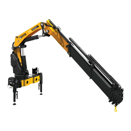
Page 20: Description Of The Loader Crane
• EFFER iX.550 HP = 51 tonne metres The loader crane is supplied in many versions from: • EFFER iX.550 HP E-4 (reach 11.2 metres) to EFFER iX.550 HP E-9 (reach 21.8 metres) The control valve V200, a controller (CombiDrive or XSDrive) and SPACEevo control system are standard equipment on these loader cranes. - Page 21 Structure and parts of the crane Hoists available in combinations: 550 E-4/5/6/7 + TI2 TI2L 550 E-7/8/9 + TI2L 550 E-6 + JIB150X-4/6 + TI2L Not compatible with manual extensions in: 550 E-7/8 + JIB150X-4/6 JDC + TI2L - JIB 150X-6 550 E-4/5/6/7/8/9 + TI4 550 E-6 + JIB150X-4/6 + TI4 Not compatible with manual...
-
Page 22: Safety Precautions And Warnings
Safety precautions and warnings 3. Safety precautions and warnings 3.1. Operating conditions You may use the crane ONLY if: • You are outdoors or in a space with sufficient ventilation. • With a mean wind velocity of less than 13.3 m/sec (approx. 29.7 mph). Refer to the wind speed table. -
Page 23: Wind Speed
Safety precautions and warnings 3.2. Wind speed Refer to the table below to correctly identify the wind speed. Wind speed averaged over 10 minutes at a height of 10 m Wind Above flat ground Characteristics Force Wind type Calm Calm, smoke rises vertically or nearly 0.0 - 0.2 vertically Slight breeze... -
Page 24: Definition Of This Loader Crane
*As specified in the documents for the equipment. Forbidden duties (unless the loader crane is specially prepared for a certain duty following authorisation from Hiab): • Installing the crane on ships or floating structures • Continuously using the crane as a production crane in assembly lines, foundries…... -
Page 25: Noise Declaration
Safety precautions and warnings • Using a personnel basket (as the crane must be certified as a MEWP crane by a notified body). Please always refer to the MEWP’s Operator's Manual. DANGER Lifting people with a crane is never allowed unless it is a MEWP crane. When working in a personnel basket, both feet must have contact with the floor of the basket. -
Page 26: Maximum Load
Safety precautions and warnings NOTE (*) This sign is included on the load diagram for some crane models. 3.3.3. Maximum load Lifting capacity Your crane has a certain lifting capacity, expressed in kNm or tm. This lifting capacity is also known as the load moment. - Page 27 Safety precautions and warnings • The reach at which you are working and the optimum position of the boom. • The optimal position for your crane is on the load plate. DANGER Never exceed the maximum weight on the load plate. NOTE To lift with the boom system heavier loads than the ones specified on the boom...
-
Page 28: Maximum Load Moment
Safety precautions and warnings WARNING Care must be taken when handling loads in the high lifting area, so the load/tool does not come into contact with the boom system. WARNING Never operate the hydraulic extensions against a solid object when the 1st boom is completely lifted. - Page 29 Safety precautions and warnings Sling length Always attach the load using the shortest possible sling. The angle between the legs of the sling must not be more than 120°. The maximum working load (or Working Load Limit - WLL) of a multi-legged sling for general purposes is calculated by multiplying the WLL of a single leg by a mode factor (refer >120º...
-
Page 30: Signals When Using A Crane
Safety precautions and warnings Heavy loads cannot be handled with the boom straight. Operate the 2nd boom to get an angle in relation to the 1st boom. Loads at the extreme limit of the working area When you lift the load with the 1st boom, make sure that you have at least a small angle with the 2nd boom. - Page 31 Safety precautions and warnings Stop all crane movements / Hold the load in position Raise the open hand, with the palm clearly visible, and arm at shoulder height. Keep the hand still. Emergency stop for all movements by the crane Raise the hands and the arms to an oblique angle.
- Page 32 Safety precautions and warnings Turn in the direction indicated Indicate the direction with the hands. Open the tool Extend the arms at shoulder height, with the palms facing downwards. Close the tool Move both hands close together. Lift the open tool a little Extend both arms at shoulder height, with the palms facing upwards.
-
Page 33: Use Of The Crane
Safety precautions and warnings Keep the tool in position briefly Raise the hand drooping slightly, with the fist clenched. 3.5. Use of the crane Starting crane operation DANGER • Make sure that you comply with the regulations of the country in which you use the crane (for example, certificate, safety helmet, and other personal protection devices). - Page 34 Safety precautions and warnings DANGER • Do not stand in front of the hydraulically operated stabiliser legs when you are operating them! • Never use the stabiliser legs as a parking brake, since the vehicle could start to slide. • Slide the stabiliser extension, on both sides of the vehicle, completely out if possible.
-
Page 35: Preparations For Use
Safety precautions and warnings 3.5.1. Preparations for use DANGER Make sure that there are no unauthorised persons within the operating range of your crane! To mark the working area correctly, think about the space that the crane will need to lift the load (direction of the lift, size of the load). -
Page 36: Crane Operation
Safety precautions and warnings Minimum distance between crane and overhead electricity lines Voltage (V) Minimum distance to an insulated Minimum distance to an uninsulated conductor conductor <500 V 0.5 m 500-40000 V 1.5 m >40000 V 2.0 m Voltages are found: up to 500 V: to buildings 500-40000 V:... - Page 37 Safety precautions and warnings In an emergency situation, push immediately any of the emergency stop buttons. This will stop all crane movements and prevent the free movement of the load. DANGER • Keep checking that there unauthorised persons within the operating reach of the crane! •...
- Page 38 Safety precautions and warnings WARNING • Never push a load along the ground, or the vehicle's load space, with the extension boom. This can cause damage to the boom system. This will lead to expensive repairs. • Never use the extension boom as a jack. This could damage the slewing bearings and the connection between the crane column and the crane base.
-
Page 39: Driving With The Crane
Safety precautions and warnings 3.5.3. Driving with the crane DANGER • Never move/drive the vehicle if there is a load suspended from the crane. • Before you move the vehicle: Check that there is no pump flow to the main control valve. The PTO or power supply must be disengaged. -
Page 40: Use Of Lifting Accessories And Interchangeable Equipment
Safety precautions and warnings 3.5.4. Use of lifting accessories and interchangeable equipment DANGER • Only interchangeable equipment intended to be used on loader cranes as specified in the documents for the equipment. • When using lifting accessories, follow the instructions supplied with the equipment! •... -
Page 41: Use Of Demountable Cranes
Safety precautions and warnings WARNING If you attach/detach equipment to/from the tip of the crane and the boom system is not in horizontal position, stay away to avoid getting caught between the boom extensions as it is normal that they can move towards each other. Be careful that your fingers do not get trapped. -
Page 42: The Control System
The control system 4. The control system 4.1. Control System SPACEevo SPACEevo is a crane control system. The control system: • Monitors the crane's operation and prevents unsafe actions. • Increases the precision with which you can work. • Makes operation easier. •... -
Page 43: Components Of The Control System
The control system DANGER Never try to repair the control system yourself. Repairs may only be made by an authorised service workshop! 4.3. Components of the control system (1) Main control valve (4) Dump valve 1 (7) Warning LED lamp (8) XSDrive controller (2) Stabiliser control valve (5) Dump valve 2... - Page 44 The control system NOTE If you use a controller to operate your crane, you can read about the symbols displayed on it in the dedicated section of this operator’s manual. By default, the symbol on the controller corresponds to the positive movement of the levers.
- Page 45 The control system Stabiliser system symbols and functions (if delivered) SYMBOLS FUNCTIONS SYMBOLS FUNCTIONS Crane Crane stabiliser stabiliser leg extension Auxiliary Auxiliary stabiliser stabiliser leg extension SYMBOLS FUNCTIONS Front auxiliary stabiliser leg Operator's Manual GB...
-
Page 46: Main Control Valve
The control system 4.5. Main control valve The crane can be operated from the main control valve, but as soon as you have selected remote control operation, it is impossible to operate the main control valve levers. The speed of a function corresponds to the extent of the lever movement, regardless of the load and other functions, as long as the oil flow is sufficient. -
Page 47: User Interface (Ui)
The control system 4.7. User Interface (UI) 4.7.1. Buttons on the User Interface (1) ON/OFF button Activates or deactivates the SPACE system. (2) Stabiliser system button Enables operation of stabiliser extensions and legs. (3) OLP release button For OLP release if the crane is in an overload situation and for temporary disconnect the dump valve function. - Page 48 The control system Stabiliser system Green LED on: Stabiliser system active. activation Green LED flashing: Stabiliser extension operation is blocked OLP Release Red LED on: OLP Red LED blinking: OLP Release active (crane, VSL or stabiliser leg) Green LED flashing: Critical error. Manual Green LED on: Manual extension mode is active.
- Page 49 The control system Blue LED on: Indicates that the ADC feature is active and the crane has full capacity. Hoist (10) Green LED on: Hoist mode. Red LED flashing fast blinking: Rope-end warning (3 turns left on the drum). Red LED blinking: 90% of OLP pressure. Red LED on: 100% of OLP pressure.
-
Page 50: Dump Valves
The control system LED test for the User Interface, see Daily inspection. 4.8. Dump valves Dump valve 1. (1) Allows operation of the crane functions. To prevent high pressure and thereby unnecessary heating of the oil there is an automatic dumping function. When no lever movement has been made for 3 seconds SPACE system opens the dump valve and the oil is returned directly to the hydraulic tank. -
Page 51: Xsdrive Controller
The control system 4.11. XSDrive controller Controller XSDrive has either four or six levers, or two or three joysticks for proportional functions programmed in the different menu selections. The controller normally communicates with the crane via radio but can also be operated via cable. -
Page 52: Indicator Leds On Xsdrive Controller
The control system Cable connection [option] The cable (2) is intended to be used for short-term operation and when pairing in conjunction with the replacement of controller or receiver. Connection is made between the controller (3) and the receiver box (1). Radio communication is automatically disabled when the cable is connected. 4.11.1. - Page 53 The control system 1st and 2nd Lower green LED on: 70% of maximum pressure. boom cylinders pressure LEDs Lower red LED flashing: 90% of maximum pressure. Lower and upper red LEDs red on: 100% of maximum pressure. Configurable Green LED on: a configurable function indication. Red LED on: a configurable function indication.
- Page 54 The control system JIB cylinder (19) Lower green LED on: 70% of maximum pressure. pressure LEDs Lower red LED flashing: 90% of maximum pressure. Lower and upper red LEDs red on: 100% of maximum pressure. Operator's Manual GB...
-
Page 55: Buttons
The control system 4.11.2. Buttons ON/OFF buttons Buttons for 9 extra ON/OFF functions (engine ON/ OFF, engine speed, horn etc.). Toggle button Not active. Menu selection Push to change between menus 1 to 6. OLP release Push and hold the button to temporarily release the OLP. -
Page 56: Menus
The control system Locking the controller Push the emergency stop button. Push and hold both arrows on the toggle button and release the emergency stop button at the same time. The 6 LEDs flash at the same time. Now you cannot operate the controller. Push the emergency stop button. -
Page 57: Standard Functions And Symbols
The control system 4.11.4. Standard functions and symbols The function corresponding to each lever or joystick, depends on the configuration of the specific crane. The table below shows examples: Controller XSDrive levers Controller XSDrive joystick 3-0-3 Controller XSDrive joystick 2-2-2 Controller XSDrive joystick 3-2-3 SAF symbols The order of the levers/buttons is customized. -
Page 58: Battery And Battery Charger Xsdrive
The control system 4.11.5. Battery and battery charger XSDrive Battery A fully charged battery provides approximately 5-8 hours use (at 25°C, 77°F) and the voltage level is approximately 8.4 V. When the battery is about to wear out an indicator LED on the controller turns steady red and the horn will sound twice. -
Page 59: Cable Connection [Option]
The control system 4.12.1. Cable connection [option] A 15-metre cable is supplied as an option with the controller. The cable is for temporary operation. The cable connects to the vehicle through the connector (1) on the crane base. When the cable (2) is connected to the controller (3), the centre display shows the symbol for cable operation. - Page 60 The control system • Time (1) It shows the time set on the control system. • Alternative display selection (2) With this button you can change the current available display in a VIEW. • Error (3) This symbol appears if the control system has an error. The centre display shows a big spanner symbol and the crane stops.
- Page 61 The control system • Battery status (7) The battery symbol shows the remaining power in the battery. The centre display shows a symbol when there is little capacity left. When the battery is low, the horn of the crane also operates a sound two times.
-
Page 62: Buttons
The control system 4.12.4. Buttons Configurable buttons OLP release The controller has six Push and hold to activate configurable push-buttons for OLP release. See section “OLP controlling features, for example release”. start/stop engine, increase/ Push to acknowledge an error. decrease rpm on the engine, etc. -
Page 63: Operational Views, Standard Functions And Symbols
The control system Locking the controller 1. Push and hold button (3) and (4) while the emergency stop button (8) is pushed. 2. Keep button (3) and (4) pushed while you pull out the emergency stop button (8). The centre display then shows a large locked padlock symbol Unlocking the controller 1. - Page 64 The control system Centre display The CRANE VIEW has as a general layout: Screen area Information Primary display (1) • Crane status • Stabiliser system status • Vehicle data Secondary display (2) • Crane status • Stabiliser system status Warnings display (3) Crane warnings when they occur Features display (4) Features status: active or not active...
- Page 65 The control system Example of sub-VIEWS for the 6 and 8 levers controller: When the operator pulls out the emergency stop button on the controller, it always starts in CRANE 1 VIEW. The sub-VIEWS in CRANE VIEW are configured in production but can be changed by Effer service personnel.
- Page 66 The control system The display also shows the stabiliser legs and extensions status: • Stabiliser leg not set to the ground (1) • Stabiliser leg set to the ground (2) • Stabiliser leg in OLP situation (3) • Stabiliser leg at the end of the stroke (4) •...
- Page 67 The control system Stabiliser Stabiliser Stabiliser Stabiliser system system extension leg function position function (out/in) (down/up) Auxiliary stabiliser system Front auxiliary stabiliser system Rear auxiliary stabiliser system IMPORTANT Each function is operated using a specific lever on the controller. If a lever is faulty or moved at startup, the lever and the function are disabled.
- Page 68 The control system TRUCK VIEWS Push the button to navigate through the different sub-VIEWS of the TRUCK VIEW. Once selected, wait to 2 seconds and the sub-VIEW selected will be displayed. These TRUCK VIEWS include the extra functions that are installed on the vehicle. Centre display The TRUCK VIEW shows on the full screen the description of the VIEW.
- Page 69 The control system SETTINGS VIEWS Push the button to select different sub-VIEWS of the SETTINGS VIEW. Then, wait about two seconds and the selected sub-VIEW will be displayed. These SETTINGS VIEWS include the different settings and features that you can activate or deactivate for your crane and controller.
- Page 70 The control system INFO VIEWS Push the button to select different sub-VIEWS of the INFO VIEWS. Then, wait two seconds and the selected sub-VIEW will be displayed. These INFO VIEWS include all the information for your crane. Centre display The INFO VIEW includes these sub-VIEWS: •...
-
Page 71: Battery And Battery Charger
The control system SAF symbols shown on the displays The order of the levers/buttons is customized. The side displays show the symbols for each lever/button. (1) SAF - fold/unfold the boom system. (2) SAF - confirm extension in. (3) SAF - not confirmed extension in. NOTE For the SAF feature, the movement of the lever (positive or negative) will be the difference between folding or unfolding the boom system. -
Page 72: Other Components Of The Control System Spaceevo
The control system LEDs status The green LED (D) on: when the charger is active. The LED (E) indicates the status of the charger and the battery: Green LED blinking: during charging the battery. Green LED on: when the battery is fully charged. Red LED blinking: when the temperature is too high. - Page 73 The control system Harnesses These are the cables to connect all the devices to the respective boxes. VIB (Vehicle Interface Box) Connection box between the vehicle and the crane. You can find this box under one of the User Interface boxes.
-
Page 74: Starting Crane Operation
Starting crane operation 5. Starting crane operation 5.1. Starting operations • General case: Put the vehicle on a flat, firm and stable surface. The 0º vehicle inclination (α) during crane operation must not be more than 3º. If this value is exceed, unintentional crane movements can occur. - Page 75 Starting crane operation Engage the PTO Activate the parking brake and place chocks under the wheels to prevent vehicle movement. Engage the PTO (Power Take Off) and bring the vehicle engine to the correct rpm. NOTE • Rpm too high: the oil in the hydraulic system might overheat. •...
-
Page 76: Set The Stabiliser System
Starting crane operation Start the controller 1. Fasten the controller to a waist belt, or shoulder-/neck strap, in the most comfortable operating position. The emergency stop button should be on the right-hand side. The operating levers must be in neutral position before start up. - Page 77 Starting crane operation Confirm view The operator must have a full view of the stabiliser system when operating it. To confirm a full view of the stabiliser system, button is pushed on the User Interface on the side where the stabiliser system is going to be operated.
-
Page 78: Stabiliser System And Ground Conditions
EFFER iX.550 HP EFFER iQ.950-1200 HP HIAB Auxiliary stabilisers: 2.3 m HIAB Auxiliary stabilisers: 5 m HIAB Auxiliary stabilisers: 6 m - 8 m HIAB Auxiliary stabilisers: 8.7 m NOTE Sign that shows the maximum force that the stabiliser legs can apply to the ground. - Page 79 Starting crane operation NOTE Sign that shows the maximum force that the auxiliary stabiliser legs can apply to the ground. DANGER Check that the extra support plates do not bend or sink into the ground. Do not lower the stabiliser legs on the edge of an embankment, soft ground, hollows, etc…...
-
Page 80: Activate The Stabiliser System
Starting crane operation 5.2.2. Activate the stabiliser system Manually-controlled stabiliser system: 1. Make sure that the manual control is active. If not, push the button on the User Interface. 2. Push the button to activate the stabiliser system operation. Controlled stabiliser system from the high seat: •... -
Page 81: Extend The Stabiliser Extensions
Starting crane operation NOTE When the sensor detects the controller, the controller vibrates and you have approximately 10 s to start the stabiliser extension movement. If you do not start the movement during this period, the connection between the controller and the sensor is disabled and the controller vibrates again. -
Page 82: Set The Stabiliser Legs
Starting crane operation Hydraulically controlled stabiliser extensions Unlock the stabiliser locking device (1) (if fitted) and extend the stabiliser extensions with the levers on the valve or the controller depending on your crane configuration. DANGER Do not stand in front of the hydraulically operated stabiliser extensions when you are operating them! 5.2.4. - Page 83 Starting crane operation DANGER Always ensure that the stabiliser legs and stabiliser extensions are in working position and securely locked. Never operate up any stabiliser leg if you have load on the crane. NOTE At the end of the operation, do a check of the levelling of the vehicle with the spirit level.
- Page 84 Starting crane operation Hydraulically controlled tiltable stabiliser legs DANGER Do not stand in the tilting area. Make sure the tilting mechanism remains unlocked during the complete tilting. Make sure the stabiliser extension is extended a little and the stabiliser leg can be rotated freely of the vehicle.
-
Page 85: Operate The Boom System Out Of Transport Position
Starting crane operation 5.3. Operate the boom system out of transport position WARNING • A crane with interchangeable equipment and/or optional components can differ from the operations described in this section. For this reason, study the operating instructions for any interchangeable equipment and/or optional components carefully. -
Page 86: Saf Semi Automatic Folding [Option]
Starting crane operation 5.3.1. SAF Semi Automatic Folding [option] SAF is a feature which allows the operator to fold or unfold the boom system in one single sequence using only one lever. Unfold the boom system semi automatically WARNING Never use SAF with mounted tools. WARNING Make sure there is enough space for the boom system to unfold/fold semi... -
Page 87: Bda Boom Deployment Assistance [Option]
Starting crane operation Select the menu for SAF on the controller. If SAF is not configured in a separate crane menu, push the button to activate it. Operate the lever on the controller until the boom system has been fully unfolded: •... -
Page 88: Operate The Boom System
Starting crane operation 5.3.3. Operate the boom system EFFER iX.550 HP When the stabiliser extensions are extended, the stabiliser extension “A” will allow the movements of the 1st boom. Operate the 2nd boom (1) against the 1st boom. Retract carefully the extensions (2). -
Page 89: During Operation
During operation 6. During operation 6.1. Features The control system provides a large number of features. Certain features are standard, others are options. 6.1.1. Controlling the crane speed with the controller XSDrive At startup, the system by default is set to full speed. To reduce the speed, push button once. -
Page 90: Supervision Of Spools
During operation Controlling the crane speed with the levers 1. Press the button on the controller for the SETTINGS VIEW. 2. Navigate to MODES sub-VIEW. 3. Change the crane speed with the appropriate lever. The centre display will show the symbol of the selected crane speed. -
Page 91: Adc Automatic Duty Control
During operation 6.1.7. ADC Automatic Duty Control The purpose of the ADC feature is to optimise the use of the steel structure. The first boom pressure sensors indicate if there is a positive or negative pressure on the first boom. Adjusted capacity •... - Page 92 During operation The VSL diagram After the installation on the truck, the installer prints unique stability diagrams for each crane. In the diagrams, each colored curve shows the cranes stable area and the maximum working pressure in the 1st boom cylinder with stabiliser extensions in different outreach.
- Page 93 During operation Stability diagram (Two ON/OFF sensor on stabiliser extensions) With two On-Off sensors, you see three curves and three positions of the stabiliser extensions Not fully extended 0-60% (shown as Crane Capacity 180° -180° 150° -150° 120° -120° Extended to 60-99% (shown as 60%) 90°...
- Page 94 During operation VSL diagram with the controller CombiDrive The VSL diagram is updated according to the real situation of the stabiliser extensions and legs status. These are different examples of the VSL diagram. The Load Chart: The software creates six different capacity diagrams with the stabiliser extensions in different positions (represented in the truck drawing).
- Page 95 During operation The three coloured curves represent the three different loads. These loads are represented by the position of the crane in each sector (degrees) and also by the outreach of the boom extensions (meters or feet and inches). The different positions of the stabiliser extensions are shown in the text over the picture diagram (D).
-
Page 96: Vsl+ (Variable Stability Logic Plus) [Option]
In order to get the maximum benefit from the VSL+ system, some of the wheels of the vehicle shall be lifted from the ground but Hiab strongly recommends that at least one wheel is braked by the parking brake and has contact with the ground. -
Page 97: Lss-V Load Stabilising System-Vertical [Option]
During operation 6.1.11. LSS-V Load stabilising system-vertical [Option] LSS-V reduces vertical oscillations in the boom system. This feature makes it easier to handle loads at long outreach. WARNING Disable LSS-V when working in confined spaces. Compensating movement can cause the crane to collide with obstacles. If LSS-V is enabled when SPACE is switched off, it will be active when SPACE is started again. -
Page 98: Olp Overload Protection
During operation 6.2. OLP Overload protection OLP is a safety feature that prevents overloading of the crane. From 90% to 100% of maximum permitted pressure, the warning LED lamps on the stabiliser legs double blink. 6.2.1. User Interface: Boom system OLP When 100% of the maximum permitted pressure is reached, OLP cuts in and stops all functions that increase the pressure. -
Page 99: Olp - Indications On The Controller
During operation 6.3. OLP - indications on the controller OLP on the XSDrive controller Boom system OLP: The cylinder LEDs indicate a percentage of maximum pressure: • 70% of maximum pressure reached - lower LED on each cylinder light green •... -
Page 100: To Release Olp
During operation Stabiliser system OLP on the CombiDrive controller If a stabiliser leg is overloaded, slewing is stopped in the direction towards the stabiliser leg where the OLP occurs. The crane stops. The centre display shows the symbol 100% and the symbol for the stabiliser leg that has overload (marked red with an X). -
Page 101: Manual Extensions [Option]
During operation NOTE In case of a crane breakdown, the use of OLP release will be part of the investigation. If the use of OLP release is too excessive, it might affect warranty. OLP release on User Interface Push and hold the button while you operate load- reducing functions. - Page 102 During operation CAUTION To operate the crane to transport position, do not forget either dismantle manual extension or place manual extension completely into the last hydraulic extension. To extend the manual extensions Locate the boom system as close as possible to the horizontal position, but low enough to reach the extension by hand.
- Page 103 During operation Activate and de-activate OLP for manual extensions on the User Interface WARNING You must switch the OLP on and off manually for additional manual extensions! Activate: Push button on the User Interface. manual extensions included OLP protection. The lifting capacity will be reduced automatically.
-
Page 104: Hydraulic Connections
During operation Activate and de-activate OLP for manual extensions on the CombiDrive controller WARNING You must switch the OLP on and off manually for additional manual extensions! Activate and deactivate with the ON-OFF buttons Push the appropriate button to activate or deactivate the feature. -
Page 105: Hydraulic Quick Couplings [Option]
During operation WARNING • Switch off the control system and the PTO before connecting or disconnecting the electrical and hydraulic connections. • Keep the electrical and hydraulic protection caps and plugs in good condition and store them in a safe place. 6.6.1. - Page 106 During operation To disconnect the hydraulic quick couplings you must: Switch off the control system. Disengage the PTO. Disconnect the hydraulic couplings, and protect them with protective caps. Reconnect the PTO and switch on the system, if needed. Operate the crane to verify that all functions work correctly.
-
Page 107: Hydraulic Quick Couplings (Multi-X) [Option]
During operation 6.6.2. Hydraulic quick couplings (MULTI-X) [option] Hydraulic quick couplings allow the connection of several hydraulic lines at the same time. WARNING • Switch off the control system and the PTO before connecting or disconnecting the connectors. • Always remove/attach first the electrical connection before the hydraulic connection. -
Page 108: Ending Crane Operation
Ending crane operation 7. Ending crane operation 7.1. SAF Semi Automatic Folding [option] SAF is a feature which allows the operator to fold or unfold the boom system in one single sequence using only one lever. Fold the boom system semi automatically WARNING Never use SAF with mounted tools. - Page 109 Ending crane operation WARNING If your crane is equipped with a hoist , change from hoist to hook operation. Displace the hoist, if needed, to the outside position before operating the crane to parking position with JIB and hoist. Make sure that the rope is on the 2nd boom support and does not pass through any pulley.
-
Page 110: Operate The Boom System Into Transport Position
Ending crane operation DANGER Pay careful attention when using this feature. Always maintain eye contact when operating the crane. During this movement, the boom system will fold itself, release the lever immediately if the boom system is about to: • Hit a person •... - Page 111 Ending crane operation 7.2.1. EFFER iX.550 HP Retract the extensions completely (1). Raise the 1st boom (2) until BDA allows you to operate the 2nd boom or β>135º. Slew the crane (3) to parking position. Check that arrows “A” are aligned.
-
Page 112: Placing The Stabiliser System In The Transport Position
Ending crane operation CAUTION Take care not to damage the 2nd boom and the support during these operations. Fold the hook. 7.3. Placing the stabiliser system in the transport position DANGER Do not stand in the stabiliser legs, tilting area. WARNING Do not put your foot on the support plate. - Page 113 Ending crane operation Non-tiltable stabiliser legs If there is an extra support plate (1) for the leg delivered, retract the stabiliser leg a little, if not, go to step 3. Remove the extra support plate (1). Retract the stabiliser leg completely. Retract the stabiliser extension completely.
- Page 114 Ending crane operation Hydraulically controlled tiltable stabiliser legs DANGER Do not stand in the tilting area. Make sure the leg remains unlocked during the complete tilting. If there is an extra support plate (4) for the leg delivered, retract the stabiliser leg a little, if not, go to step 3.
- Page 115 Ending crane operation Retract the stabiliser extensions The procedure of retracting the stabiliser extensions differs depending on the type of stabiliser extensions. Repeat the instructions for the stabiliser extension on the other side of the vehicle. For auxiliary stabiliser system [option]: Repeat the process. Hydraulically controlled stabiliser extensions DANGER Before you retract the stabiliser extensions:...
-
Page 116: Switching Off The Control System
Ending crane operation 7.4. Switching off the control system • Switch off the control system with the ON/OFF button If you are using the remote controller: • Push the emergency stop button on the controller and switch off the control system. •... - Page 117 Ending crane operation Operate the crane to transport position: DANGER • Always use the controller for this operation if it is possible. • With the crane safety system disconnected: ◦ First, you must fully retract all the boom extensions, crane and JIB [option].
-
Page 118: Emergency Operation To Bring The Stabiliser System To Transport Position
Ending crane operation 7.5.2. EMERGENCY operation to bring the stabiliser system to transport position DANGER • The use of any emergency operation is under your direct responsibility as operator of the crane. • You must be qualified and correctly trained in the emergency operation. Pay careful attention when operating from the operator station (crushing, falling, etc...) and watch out for hidden hazards (low visibility, narrow spaces, etc...). -
Page 119: Separate Emergency Lever [Option]
Ending crane operation Operate the stabiliser system to parking position: If electrical power supply is available, always use the controller to bring the stabiliser system to a safe transport position. DANGER Stay in a safety area during this operation. If electrical power supply is not available, use the levers on the main control valve or the separate emergency lever supplied to bring the stabiliser system to a safe transport position. -
Page 120: Transport Warning
Ending crane operation Emergency lever with the control valve V200 (crane functions) You must use this side of the emergency lever to operate this control valve Emergency lever with the control valve V80R (stabiliser functions) You must use this side of the emergency lever to operate this control valve 7.6. - Page 121 Ending crane operation • A warning, visible and audible from the driving position for transport, indicates when the crane height exceeds a predetermined maximum and when the stabiliser extensions/stabiliser legs are not locked in the transport position. • The audible warning silenced acknowledgement button [option] or by a signal...
-
Page 122: Maintenance And Service
Maintenance and Service 8. Maintenance and Service 8.1. Service No welding/drilling work on the crane DANGER • Do not do any welding work on the crane. Welding work on the crane may only be carried out by an authorised service workshop. -
Page 123: Warranty
Maintenance and Service Leaking coupling: a. Tighten the coupling with a spanner. b. If tightening does not help, contact an authorised service workshop. Small leak on a line or hose: a. Determine if you can still park the crane. b. If you can, park the crane and go to an authorised service workshop. c. - Page 124 Maintenance and Service Maintenance intervals: • Carried out by the operator: daily and monthly inspection. • Carried out by an authorised service workshop: ◦ 1st service: to be made after 50 hours of use. ◦ Regular service: to be made when one of these conditions are met: ▪...
-
Page 125: Daily Inspection
Maintenance and Service NOTE Always lubricate after cleaning the crane. WARNING Keep the devices to go into the control station (handles, supports, platforms...) clean from oil, grease and dirt to prevent slipping and falling. 8.3.1. Daily inspection Refer to the daily inspection checklist at the end of this manual to photocopy. Presence of signs and symbols •... - Page 126 Maintenance and Service Controller • Do a check of the controller functionality. Crane structure • Check for damage to the crane structure (e.g. any formation of cracks). DANGER In the event of damage that presents a safety risk: • Do not use the crane. •...
- Page 127 Maintenance and Service Hooks Always keep the hook clean. Use a cloth to wipe away any dirt. Before every working shift: • Do an inspection of the general conditions of the Hook (1) for deformation (stretched, cracked, twisted, excessive wear…) and surface damages with significant depth (such as from chemicals or heat).
- Page 128 Maintenance and Service DANGER In the event of damage or worn to prevent a safety risk: • Do not use the hook. • Have the damage repaired immediately by an authorised service workshop. Lifting accessories, interchangeable equipment and optional crane components •...
- Page 129 Maintenance and Service • Check oil level in the tank. If necessary, fill to correct level. NOTE Always place the vehicle on level ground with the crane in transport position while checking the oil. Oil level in the slewing motors and condition •...
-
Page 130: Monthly Inspection And Maintenance
Maintenance and Service 8.3.2. Monthly inspection and maintenance NOTE Refer to the monthly inspection checklist at the end of this manual to photocopy. In addition to the daily inspection, carry out the following tasks each month: Piston rods • In cases where the cylinder piston rod is exposed to pollution due to the parking location, the chromed surfaces must be cleaned and oiled to prevent corrosion. - Page 131 Maintenance and Service NOTE If the workshop is equipped and the personnel prepared to do a test of the oil quality and think that the oil change is not needed, they can postpone it on their own responsibility. Oil in the slewing gearboxes •...
-
Page 132: Lubrication
Maintenance and Service 8.4. Lubrication General greasing of the cranes Incorrect or insufficient lubrication of a crane is the number one cause of premature failure. WARNING Before and after a long stop of the crane, lubrication is absolutely necessary. This is especially important after a winter shutdown. -
Page 133: Lubrication Schedule
Maintenance and Service Use a Teflon grease spray to lubricate the extensions and mobile parts. 8.4.1. Lubrication schedule Lubricate after every 16 hours of use. Lubricate after every 50 hours of use. Grease after every 50 hours of use. Operator's Manual GB... -
Page 134: Greasing The Slewing Bearing (Internal Gear Teeth)
Maintenance and Service 8.4.2. Greasing the slewing bearing (internal gear teeth) 1. Grease through the grease nipple in the cover (1). 2. Slew the crane a bit and grease again. 3. Make sure that the slewing bearing is fully greased: a. -
Page 135: Greases For The Slewing Bearing And The Bearing Assembly
Maintenance and Service 8.4.4. Greases for the slewing bearing and the bearing assembly 8.4.5. Lubrication of slide pads in the boom system Clean the surfaces and remove with a spatula all abrasive material (dirt, sand, shavings), and where possible, the old grease. Side slide pads •... -
Page 136: Lubrication Of The Hooks
Maintenance and Service Recommended greases: • Upper / lower slide pads (Black / White colour): BP LS EP 2, ESSO UNIWAY EP2 N, AGIP GR MU/EP3, NYNÄS UNIFETT EP. • Upper / lower slide pads (Grey / Purple colour): LAGERMEISTER WHS 2002, STABYL TA •... -
Page 137: Checking And Topping Up Oil Levels
Maintenance and Service 8.5. Checking and topping up oil levels 8.5.1. Slewing motors gearbox Supplier recommendation: Have the oil changed after the first 150 operating hours approximately. Then, repeat approx. every 2000 or 4000 operating hours depending on working conditions or at least once a year. Recommended oil: Use a hypoid oil, type API GL-5, SAE J2360 (Formerly MIL-L-2105),viscosity SAE-80W-90, cleanliness NAS 1638:8. - Page 138 Maintenance and Service Oil filling / Top up Make sure that the required equipment to fill the tank is fully clean. Put the crane in the parked position. Clean the area around the oil filler cap. Fill with oil up to the max level indicator. CAUTION •...
- Page 139 -15°C to 90°C (5°F to 194°F) -5°C to 90°C (23°F to 194°F) The recommended viscosity during normal working conditions is between 16 and 40cSt. Hiab strongly recommends an oil working temperature below 70 °C (158 °F). If necessary consider an oil cooler or heater. NOTE If you need to work at a temperature below -25 °C (-13 °F), contact an authorised...
-
Page 140: Replacement Of Filters
Maintenance and Service CAUTION Vegetable oils do not meet Hiab requirements and must not be used. After filling the tank 1. Operate each crane function to its end positions. 2. Operate the crane to parked position. 3. Check and top up the oil tank to max level on the tank gauge. -
Page 141: Bleeding Air From The Hydraulic System
Maintenance and Service 8.7. Bleeding air from the hydraulic system Bleed the air from the hydraulic system: • after changing the hydraulic oil • after working on the hydraulic system • if your crane works slowly or jerkily • if your crane has not been used for a long time WARNING Air in the hydraulic system can lead to faults and damage To bleed the air from the hydraulic system, proceed as follows:... -
Page 142: Troubleshooting
Maintenance and Service 8.8. Troubleshooting 8.8.1. Main fuses If the processor detects a fault, this must be rectified immediately. Fault Probable Action cause The control system does not work Defective 1. Replace faulty fuses in the: at all. fuses. - vehicle - vehicle interface box (VIB) The indicator light next to ON/OFF - relay box... -
Page 143: Faults On The Crane
Maintenance and Service 8.8.2. Faults on the crane Faults in the crane must be rectified immediately. DANGER • Only correct yourself the faults that according to the table you may rectify. • Follow the instructions exactly! • All other faults must be corrected by personnel in an authorised service workshop! Fault Probable cause... - Page 144 Maintenance and Service Fault Probable cause Action Insufficient oil in the Top up the oil tank. hydraulic system. Top up the oil in the Insufficient oil in the slewing housing to the slewing housing. required level. Irregular slewing movements and unusual noises in cranes with rack The upper slewing and pinion slewing system.
- Page 145 Maintenance and Service Fault Probable cause Action Load holding valves Go to an authorised service on the 1st boom or workshop. Boom system cannot keep the load 2nd boom damaged. height, and it goes down by itself. Cylinder internal Go to an authorised service leakage.
-
Page 146: Display
Maintenance and Service 8.8.3. Display The display has three menu items: Error codes, Timers & Counters and VSL. These items are shown on the screen when the display is first engaged. To be able to select an item push the menu toggle button or the OK button. In the bottom left of the screen the name of the item currently highlighted is shown. -
Page 147: Gateway Connection Box [Option]
Maintenance and Service If you select this symbol, the truck VSL diagram shows six sectors surrounding the crane, and in each sector there VSL 100 is a percentage. A percentage of 90 indicates that the maximum pressure available in the 1st boom cylinder is reduced to 90% in this sector to guarantee full stability. - Page 148 Maintenance and Service The LED is steady green = the gateway is operational and all connections are correct. The LED shows a green blinking light = there is an error in the connection. The LED is off = the gateway is off. ERRORS The STATUS LED (2) shows the status of the connection between the gateway, SPACE, GPS, and 3G/4G.
- Page 149 Maintenance and Service Example: Several errors exist in the system. Error 2 and 3 exist in the system. NOTE If error 1, 2, and 3 exist in the same time, do a check that you have the correct Gateway kit (EU for European Union or US for United States, Canada and Mexico).
-
Page 150: Decommissioning
Decommissioning 9. Decommissioning 9.1. Decommissioning a crane NOTE Only qualified companies can remove the crane from the truck and dispose of it. Cranes are designed and manufactured taking the environment into consideration. Environmental requirements and soundness have been considered when selecting the raw materials. The metal parts are designed to achieve a light and durable construction;... - Page 151 Decommissioning Unsorted waste should be delivered to a landfill. • Drained hydraulic hoses, electrical wires, control cables, seat, hydraulic cylinder seals, lights, small plastic and rubber parts. Hazardous waste is delivered to a collection point for hazardous waste. • Oils: hydraulic oil, transmission oil from the slewing system •...
-
Page 152: Technical Data
Technical Data 10. Technical Data 10.1. Load plate table The Installer must fill in the valid meters (m) and kilos (kg) in this table, following instructions given in the Installation instructions. The enclosed Technical Data must be stored together with this Operator’s manual. Operator's Manual GB... -
Page 153: Identification Of The Loader Crane
Technical Data 10.2. Identification of the loader crane The information below is to be filled in by the installer. The same information will be found on the serial number plate on the crane: Mark: EFFER Type: ......Serial number: ......Manufact. -
Page 154: Daily Inspection Checklist
Permission to reproduce this checklist is granted; however please note that only the original document owned by Hiab will contain necessary amendments and updates. Hiab shall not be held liable if the copy in your possession does not contain the latest changes. -
Page 155: Monthly Inspection Checklist
Permission to reproduce this checklist is granted; however please note that only the original document owned by Hiab will contain necessary amendments and updates. Hiab shall not be held liable if the copy in your possession does not contain the latest changes. - Page 156 This page is intentionally left blank. Operator's Manual GB...
- Page 158 © EFFER All rights reserved. No part of this publication may be reproduced or copied in any form or by any means without written permission from EFFER. EFFER is part of Cargotec Corporation.
Need help?
Do you have a question about the EFFER iX.550 HP and is the answer not in the manual?
Questions and answers