Table of Contents
Advertisement
Quick Links
Advertisement
Table of Contents

Related Manuals for HIAB EFFER 65D X4 CE


Summary of Contents for HIAB EFFER 65D X4 CE
- Page 1 Operator's Manual GB 737 3155...
- Page 3 Congratulations! You are now the owner of a quality Product manufactured by Hiab (part of Cargotec Corporation). The aim of this manual is to help you handle, maintain your crane safely and with full satisfaction. This Manual provides detailed information about your Product, its control systems and its practical management and maintenance.
- Page 4 This page is intentionally left blank.
-
Page 5: Table Of Contents
Table of Contents 1. Introduction ..................9 1.1. Target group and scope of this manual ..........9 1.2. The Machinery Directive 2006/42/EC ..........10 1.3. The Machinery (Safety) Regulations 2008 ......... 11 1.4. Cleanliness certificate ..............12 1.5. Indications in the Operator’s Manual ..........12 2. - Page 6 4.9.4. Standard function symbols ..........57 4.9.5. Battery and battery charger XSDrive ........57 4.10. Pressure-reducer filter ............... 58 4.11. Control platform [option] ............. 59 5. Starting crane operation ................ 60 5.1. Starting operations ..............60 5.2. Set the stabiliser system .............. 62 5.2.1.
- Page 7 8.3.8. Change of rope ............. 112 8.3.9. Maintenance and monitoring of rope end ....... 115 8.4. Lubrication ................115 8.4.1. Lubrication schedule ............117 8.4.2. Greasing the upper column bearing and three-point bridge ... 118 8.4.3. Lubrication of the column bearings ........118 8.4.4.
- Page 8 This page is intentionally left blank. Operator's Manual GB...
-
Page 9: Introduction
Introduction 1. Introduction 1.1. Target group and scope of this manual This manual describes: • Operation • Safety precautions and warnings • The crane control system • Maintenance and troubleshooting Enclosed to this manual the Installer will provide: • Technical Data for your crane •... -
Page 10: The Machinery Directive 2006/42/Ec
Introduction NOTE Hiab, or a third party designated by Hiab, shall at all times have the right to (i) install, maintain and dismantle a remote diagnostics device in and from the Products; and (ii) access, send, receive, collect, store, copy, aggregate, combine... -
Page 11: The Machinery (Safety) Regulations 2008
Machinery (Safety) Regulations 2008 • Business name and full address where the crane is manufactured (2): Factory addresses: Hiab Cranes S.L.U. Pol. Ind. Malpica, calle E, 86 50016 Zaragoza, Spain Cargotec Poland Sp. z o. o. Ul. Metalowa 2, 73-102 Stargard, Poland ·... -
Page 12: Cleanliness Certificate
Introduction 1.4. Cleanliness certificate All Hiab equipment has been tested and certified at the factory according to the Hiab Standard C250.52 that defines the Cleanliness Requirements for Hydraulic Systems. This means that they fulfil the cleanliness class 20/18/14 measured by the ISO 4406 standard. - Page 13 Introduction Tip to make the work easier to carry out. The symbol for reference to a component in an illustration. (1) Refers to a component in an illustration. [option]: Indication for parts that are not standard for the crane, but are optional. Not all options are available for your crane.
- Page 14 Introduction WARNING • Never clean the electronic system, plastic components, signs, or bearings with a high-pressure jet cleaner. It could cause damage. • Never expose the electronic system to high electrical voltages. This could damage the control system. • Never immerse the controller in water or other liquid. This will make the controller unusable.
-
Page 15: Structure And Parts Of The Crane
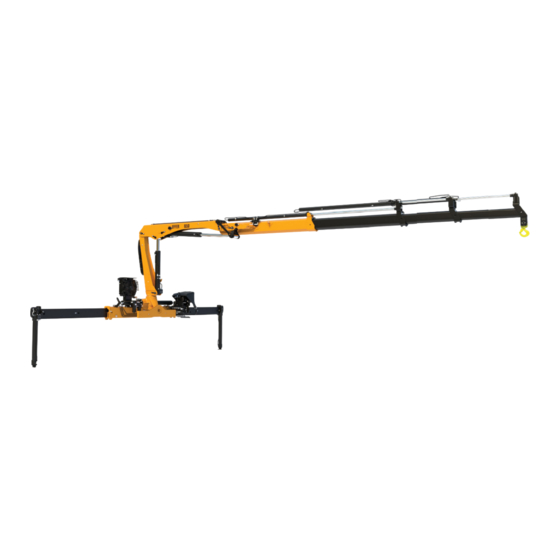
Structure and parts of the crane 2. Structure and parts of the crane 2.1. Main groups This crane consists of the following main groups: (1) Control station (6) 2nd boom (11) Oil tank (12) Hoist [option] (2) Stabiliser system (7) Boom extensions (13) Manual extensions (3) Base / Three-point bridge (8) 1st boom cylinder... -
Page 16: Crane Base With Column And Slewing System
Structure and parts of the crane 2.2. Crane base with column and slewing system The crane base, column and the slewing system consist of the following components: (1) Crane base (2) Stabiliser beam (3) Three-point bridge (4) Column (5) Rack and pinion slewing system. 2.3. -
Page 17: Boom System
Structure and parts of the crane 2.4. Boom system The boom system consists of the following main parts: (1) 1st boom (2) 2nd boom (3) Hydraulic extensions The length of the hydraulic extension depends on the type of crane. (4) Manual extensions [option] (5) Hoist [option] And optional interchangeable equipment such as: (6) Rope guide [option]... - Page 18 Structure and parts of the crane Manual extensions [option] The manual extension is slid by hand into the hydraulic extension. Hoist [option] The hoist is an optional crane component which permits load handling without any or only limited boom movement. An obvious advantage is that the hoist makes it possible to handle loads far below ground level.
-
Page 19: Operating System - Hydraulic Components
Structure and parts of the crane Lifting accessories [option] Equipment placed between the holding device of lifting machinery and the load is considered as a lifting accessory. 2.5. Operating system - hydraulic components The operating system consists of the following hydraulic components: (1) Oil tank (5) Stabiliser control valve [option] (11) Return filter... -
Page 20: Lhv Load Holding Valves
Structure and parts of the crane 2.6. LHV Load holding valves All cylinders are equipped with load-holding valves as a safety device. After a crane movement, they hold the crane in position, also in the unlikely event of a burst hose. If there is a leak or a component fractures, such as a pipe, hose or coupling, the load-holding valves will stop the booms from collapsing down, even when the hydraulic... - Page 21 Structure and parts of the crane NOTE The exact technical information for your crane is shown in the Technical Data. Operator's Manual GB...
-
Page 22: Safety Precautions And Warnings
Safety precautions and warnings 3. Safety precautions and warnings 3.1. Operating conditions You may use the crane ONLY if: • You are outdoors or in a space with sufficient ventilation. • With a mean wind velocity of less than 13.3 m/sec (approx. 29.7 mph). Refer to the wind speed table. -
Page 23: Wind Speed
Safety precautions and warnings 3.2. Wind speed Refer to the table below to correctly identify the wind speed. Wind speed averaged over 10 minutes at a height of 10 m Wind Above flat ground Characteristics Force Wind type Calm Calm, smoke rises vertically or nearly 0.0 - 0.2 vertically Slight breeze... -
Page 24: Definition Of This Loader Crane
*As specified in the documents for the equipment. Forbidden duties (unless the loader crane is specially prepared for a certain duty following authorisation from Hiab): • Installing the crane on ships or floating structures • Continuously using the crane as a production crane in assembly lines, foundries…... -
Page 25: Determination - Hoist
Safety precautions and warnings • Using a personnel basket (as the crane must be certified as a MEWP crane by a notified body). Please always refer to the MEWP’s Operator's Manual. DANGER Lifting people with a crane is never allowed unless it is a MEWP crane. When working in a personnel basket, both feet must have contact with the floor of the basket. -
Page 26: Signs On The Crane
Safety precautions and warnings 3.3.3. Signs on the crane EFFER XXXC B XXXX XXXX XXXX XXXX XXXX 10.7 12.8 15.0 17.4 MAX 150 kg xxx xxxx 3.3.4. Maximum load Lifting capacity Your crane has a certain lifting capacity, expressed in kNm or tm. This lifting capacity is also known as the load moment. - Page 27 Safety precautions and warnings Load plate On the plate is the maximum weight that you may lift at a given reach, with the 1st boom in the optimum position. In chapter Technical Data in this manual you will find these values for your crane.
-
Page 28: Maximum Load Moment
Safety precautions and warnings WARNING Care must be taken when handling loads in the high lifting area, so the load/tool does not come into contact with the boom system. WARNING Never operate the hydraulic extensions against a solid object when the first boom is completely lifted. - Page 29 Safety precautions and warnings Sling length Always attach the load using the shortest possible sling. The angle between the legs of the sling must not be more than 120°. The maximum working load (or Working Load Limit - WLL) of a multi-legged sling for general purposes is calculated by multiplying the WLL of a single leg by a mode factor (refer >120º...
-
Page 30: Lifting Loads With Hoist
In this way, you will also prevent the hydraulic system from heating up quickly. 3.3.6. Lifting loads with hoist DANGER • Use only Hiab original ropes or a rope that meets Hiab's specifications. • Check and clean hoist rope regularly but not using high pressure fluid jets neither steam jets. -
Page 31: Signals When Using A Crane
Safety precautions and warnings 3.4. Signals when using a crane DANGER • If it is not possible to see the load and the entire working area clearly, the crane operator must follow the instructions and signals given by a qualified person. •... - Page 32 Safety precautions and warnings Emergency stop for all movements by the crane Raise the hands and the arms to an oblique angle. Very short movement Place the hands a very short distance apart, with the palms facing each other. The hands may be held either horizontally or vertically.
- Page 33 Safety precautions and warnings Open the tool Extend the arms at shoulder height, with the palms facing downwards. Close the tool Move both hands close together. Lift the open tool a little Extend both arms at shoulder height, with the palms facing upwards.
-
Page 34: Use Of The Crane
Safety precautions and warnings 3.5. Use of the crane Starting crane operation DANGER • Make sure that you comply with the regulations of the country in which you use the crane (for example, certificate, safety helmet, and other personal protection devices). -
Page 35: Preparations For Use
Safety precautions and warnings WARNING • Use low force when you put the stabiliser legs on the ground. • Do not raise the vehicle with the stabiliser legs! If you do, you can cause damage to the stabiliser legs. • Check that the interchangeable equipment and lifting accessories are in good condition! Interchangeable equipment is usually attached to the boom tip (e.g. - Page 36 Safety precautions and warnings DANGER • If a part of the crane comes in contact with an electricity line, you will be electrocuted! • Always keep following minimum distances between crane overhead electricity lines, unless otherwise prescribed by national rules. Minimum distance between crane and overhead electricity lines Voltage (V) Minimum distance to an insulated...
-
Page 37: Crane Operation
Safety precautions and warnings WARNING Make sure that you know the position of all the emergency stop buttons on your crane and on the controller. 3.5.2. Crane operation DANGER Your crane has a control system. The control system will help you to work safely. Nevertheless, you remain responsible for safe use of the crane! Therefore, always work according to the operating instructions! In an emergency situation, push immediately any of the emergency stop buttons. - Page 38 Safety precautions and warnings WARNING • Never push a load along the ground, or the vehicle's load space, with the extension boom. This can cause damage to the boom system. This will lead to expensive repairs. • Never use the extension boom as a jack. This could damage the slewing bearings and the connection between the crane column and the crane base.
- Page 39 Safety precautions and warnings NOTE The exact positions for your crane can change from the image below. Slew the crane slowly in each direction to the slewing stop (B). Record the slewing stop positions. CAUTION To prevent damage to your crane base, reduce the slewing speed in the area (A) before reaching the slewing stops (B).
-
Page 40: Driving With The Crane
Safety precautions and warnings 3.5.3. Driving with the crane DANGER • Never move/drive the vehicle if there is a load suspended from the crane. • Before you move the vehicle: Check that there is no pump flow to the main control valve. The PTO or power supply must be disengaged. - Page 41 Safety precautions and warnings below ground level. Lifting and lowering are achieved by winding/ unwinding the rope. A number of auxiliary components are needed, such as intermediate pulleys and a hook pulley. As an option, a snatch block can be installed to multiply the lifting capacity. The operator should take care during hoist operation that the rope is not pulled off the drum completely.
-
Page 42: Use Of Lifting Accessories And Interchangeable Equipment
Safety precautions and warnings 3.5.5. Use of lifting accessories and interchangeable equipment DANGER • Only interchangeable equipment intended to be used on loader cranes as specified in the documents for the equipment. • When using lifting accessories, follow the instructions supplied with the equipment! •... -
Page 43: Use Of Demountable Cranes
Safety precautions and warnings WARNING If you attach/detach equipment to/from the tip of the crane and the boom system is not in horizontal position, stay away to avoid getting caught between the boom extensions as it is normal that they can move towards each other. Be careful that your fingers do not get trapped. -
Page 44: The Control System
The control system 4. The control system 4.1. Control System SPACE X4 Space X4 is a crane control system. The control system: • Monitors the crane's operation and prevents unsafe actions. • Increases the precision with which you can work. •... -
Page 45: Components Of The Control System
The control system DANGER Never try to repair the control system yourself. Repairs may only be made by an authorised service workshop! 4.3. Components of the control system (1) Main control valve (2) User panel SPACE X4-UI (3) Warning lamp (4) XSDrive controller (5) Pressure-reducer filter 4.4. - Page 46 The control system • On the control valve levers. • On the controller (If delivered). NOTE If you use a controller to operate your crane, you can read about the symbols displayed on it in the dedicated section of this operator’s manual. By default, the symbol on the controller corresponds to the positive movement of the levers.
- Page 47 The control system Extra symbols and functions (if delivered) SYMBOLS FUNCTIONS SYMBOLS FUNCTIONS Hoist JIB cylinder Rotation tool Tool 2 extensions Operator's Manual GB...
-
Page 48: Main Control Valve
The control system Stabiliser system symbols and functions (if delivered) SYMBOLS FUNCTIONS SYMBOLS FUNCTIONS Crane Crane stabiliser stabiliser leg extension Auxiliary Auxiliary stabiliser stabiliser leg extension SYMBOLS FUNCTIONS Front auxiliary stabiliser leg 4.5. Main control valve The speed of a function corresponds to the extent of the lever movement, as long as the oil flow is sufficient. -
Page 49: Different Stabiliser Control Valves
The control system Standard functions and symbols The order of the functions is customized for each crane. The image on the right shows an example of a main control valve functions placed on the base. NOTE For remote-operated cranes the levers on the main control valve are only for emergency operation. -
Page 50: User Panel
The control system 4.7. User panel Buttons: (1) ON/OFF button Activates or deactivates the SPACE system. (2) Stabiliser system button Enables operation of stabiliser extensions and legs. (3) OLP release button For OLP release if the crane is in an overload situation and for temporary disconnect the dump valve function. - Page 51 The control system Power ON/OFF Green light on: The system is on. Green light blinking: System on and the stop button has been pushed. Green light flashing: APO emergency operation time running. Red light flashing: CAN communication has been lost/ APO override time running Stabiliser system Green light on: Stabiliser system active.
- Page 52 The control system Hoist (10) Green light on: Hoist mode. Red light flashing: 3 rolls left on the hoist drum. Red light blinking: 90% of OLP pressure. Red light on: 100% of OLP pressure. (11) Blue light on: Outermost extension fully retracted and the JIB has increased capacity (JDC mode).
-
Page 53: Warning Lamps
The control system 4.8. Warning lamps A warning lamp on each stabiliser leg is used to warn the surrounding about ongoing activity, by amber light indication. A warning lamp also gives information to the operator about the different statuses of the crane. System ON: the stabiliser leg lamps light up Remote control ON: the stabiliser leg lamps blink 90% of maximum permitted load and OLP: the stabiliser leg... - Page 54 The control system Service Red light on: Error detected in the system. Battery Red light on: Low power Hoist LED Red light flashing: 90% of maximum pressure Red light on: 100% of maximum pressure Red light on: VSL-OLP. Vehicle has reached a stability limit.
-
Page 55: Buttons
The control system 4.9.2. Buttons ON/OFF buttons Buttons for 7 extra ON/OFF functions (engine ON/OFF, [option] engine speed, horn etc.) Menu selection Push to change between menus 1 to 4. OLP release Push and hold the button while you operate a pressure reducing function. -
Page 56: Menus
The control system 1. Push the emergency stop button. 2. Push and hold both arrows on the toggle button and release the emergency stop button at the same time. 3. The 4 LEDs flash at the same time. Now you cannot operate the controller. 4. -
Page 57: Standard Function Symbols
The control system MENU 4 [option] Similar to menu 3 but for extra stabiliser legs 4.9.4. Standard function symbols The function corresponding to each lever depends on the configuration of the specific crane. The table below shows examples: XSDrive levers 6F XSDrive levers 4F SAF symbols The order of the levers/buttons is customized. -
Page 58: Pressure-Reducer Filter
The control system Battery charger The battery charger is to be fitted in a protected environment, preferably in the cab. LED (1) is lit continuously when the battery charger is ready for use. Place the battery in the charger. LED (2) flashes slowly during recharging and has a steady light when the battery is fully charged. -
Page 59: Control Platform [Option]
The control system 4.11. Control platform [option] The platform is placed on the left side of the crane, with perforated anti-slip plate. • For manually controlled cranes: The platform is equipped for using tools and operated using six levers with control valve on the top. •... -
Page 60: Starting Crane Operation
Starting crane operation 5. Starting crane operation 5.1. Starting operations • General case: Place the vehicle on a flat and firm surface. The vehicle 0º inclination during crane operation must not be more than allowed in the Technical Data for your crane. If this value is exceeded, unintentional crane movements can 5º... - Page 61 Starting crane operation Engage the PTO Activate the parking brake and place chocks under the wheels to prevent vehicle movement. Engage the PTO (Power Take Off) and bring the vehicle engine to the correct rpm. NOTE • Rpm too high: the oil in the hydraulic system might overheat. •...
-
Page 62: Set The Stabiliser System
Starting crane operation Start the controller 1. Fasten the controller to a waist belt, or shoulder-/neck strap, in the most comfortable operating position. The emergency stop button should be on the right-hand side. 2. Push button on the User Interface. The LED above that button will blink. - Page 63 Starting crane operation Stability sector indication The operator must have a full view of the stabiliser system when operating it. To confirm a full view of the stabiliser system, button is pushed on the User Interface on the side where the stabiliser system is going to be operated.
-
Page 64: Activate The Stabiliser System
Starting crane operation DANGER Check that the extra support plates do not bend or sink into the ground. Do not lower the stabiliser legs on the edge of an embankment, soft ground, hollows, etc… Lower the stabiliser legs only on to a flat, firm and stable surface. 5.2.1. -
Page 65: Set The Stabiliser Legs
Starting crane operation Manually controlled stabiliser extensions Unlock Stabiliser locking devices (2) and (3). Take a firm grip around handle (1), and pull to extend the stabiliser extension and lock with the handle (3). Hydraulically controlled stabiliser extensions Unlock the Stabiliser locking device (2) [option] and extend the stabiliser extensions with the levers on the valve or the controller depending on your crane configuration. - Page 66 Starting crane operation WARNING Take care not to lower the stabiliser leg onto your foot. NOTE For cranes with VSL the stabiliser leg downward movement is automatically stopped at a pre-given force level. To exceed this pre-given force level, operate the stabiliser leg down once again.
- Page 67 Starting crane operation Non-tiltable stabiliser legs Make sure that the stabiliser extensions are extended. Operate the stabiliser leg downwards until it is set to the ground. Manual tiltable stabiliser legs 1. Make sure the stabiliser extensions are extended a little ②...
-
Page 68: Operate The Boom System Out Of Transport Position
Starting crane operation Make sure the stabiliser extension is extended and the stabiliser leg can rotate freely of the vehicle. Place your right hand on the handle (3) while unlocking the stabiliser leg (4) with your left hand. Make sure the leg drops in a controlled movement until it stops. -
Page 69: Saf Semi Automatic Folding [Option]
Starting crane operation DANGER Always operate a manually controlled crane from the position shown in the image! 1. If the stabiliser system is manually controlled, push button on the User Interface to activate remote control. 2. If using remote control, push button (1) on the controller to change the menu into crane operation. - Page 70 Starting crane operation WARNING Make sure there is enough space for the boom system to unfold/fold semi automatically. If the situation does not allow SAF, use crane mode to operate the boom system out of/into the parked position. WARNING If your crane has manual extensions, make sure that they are totally retracted or removed before operating the crane with the SAF feature.
-
Page 71: Bda Boom Deployment Assistance [Option]
Starting crane operation DANGER Pay careful attention when using this feature. Always maintain eye contact when operating the crane. During this movement, the boom system will unfold itself, release the lever immediately if the boom system is about to: • Hit a person •... -
Page 72: Operate The Boom System
Starting crane operation 5.3.3. Operate the boom system Operate the 2nd boom (1) fully against the underside of the 1st boom (2). Raise the 1st boom (2). As soon as the 1st boom is raised to an angle where the 2nd boom can go free from the crane base, raise the 2nd boom (3). -
Page 73: During Operation
During operation 6. During operation 6.1. Features The control system provides a large number of features. Certain features are standard, others are options. 6.1.1. Controlling the crane speed with the controller XSDrive At startup, the system by default is set to full speed. To reduce the speed, push button once. -
Page 74: Ado Automatic Dumping Of Oil
During operation 2. Parking brake controlled power off. Through the vehicle’s parking brake, APO offers a feature which ensures that the control system is off when the vehicle is moving. When parking brake is released, the control system receives a signal and shuts OFF. For emergency operation During 5 seconds, it is possible to activate the control system by pushing the ON/OFF button on the User Interface. - Page 75 During operation The VSL diagram After the installation on the truck, the installer prints unique stability diagrams for each crane. In the diagrams, each colored curve shows the cranes stable area and the maximum working pressure in the 1st boom cylinder with stabiliser extensions in different outreach.
- Page 76 During operation Stability diagram (Two ON/OFF sensor on stabiliser extensions) With two On-Off sensors, you see three curves and three positions of the stabiliser extensions Not fully extended 0-60% (shown as Crane Capacity 180° -180° 150° -150° 120° -120° Extended to 60-99% (shown as 60%) 90°...
- Page 77 During operation The Lifting Capacity Diagram: The software creates six different capacity diagrams with the stabiliser extensions in different positions (represented in the truck drawing). For cranes with JIB, another six XXXXX XXXXX XXXX XXXX XXXX XXXX XXXX XXXX XXXX XXXX XXXX XXXX...
-
Page 78: Lss-V Load Stabilising System-Vertical [Option]
During operation 6.1.8. LSS-V Load stabilising system-vertical [Option] LSS-V reduces vertical oscillations in the boom system. This feature makes it easier to handle loads at long outreach. WARNING Disable LSS-V when working in confined spaces. Compensating movement can cause the crane to collide with obstacles. If LSS-V is enabled when SPACE is switched off, it will be active when SPACE is started again. -
Page 79: Olp - Indications On The Controller
During operation Stabiliser system OLP If a stabiliser leg is overloaded, slewing is stopped in the direction towards the stabiliser leg where the OLP occurs. The crane stops. The warning lamps on the stabiliser legs will blink. On the User Interface, the LED for the overloaded stabiliser leg will light red. -
Page 80: Manual Extensions [Option]
During operation DANGER Only use the OLP release to get the crane out of a locked position. Never use the OLP release to overload the crane deliberately! NOTE In case of a crane breakdown, the use of OLP release will be part of the investigation. - Page 81 During operation To extend the manual extensions Locate the boom system as close as possible to the horizontal position, but low enough to reach the extension by hand. Stop the crane, by pressing the stop button. Remove the locking device (1) and the locking pin (2). Extend the manual extension fully by hand.
- Page 82 During operation Activate and de-activate OLP for manual extensions on the User Interface WARNING You must switch the OLP on and off manually for additional manual extensions! Activate: Push button on the User Interface. manual extensions included OLP protection. The lifting capacity will be reduced automatically.
-
Page 83: How To Change From Hoist To Hook Operation
During operation 6.5. How to change from hoist to hook operation Remove the counterweight: Remove the locking pin (1), the nut (2) and the pin (3). Release the rope. Remove the rope from the top roller: Remove the locking pin (4), the roller (5) and the securing pin (6). Pass the rope through the top roller. - Page 84 During operation Remove the rope from the intermediate pulleys and rope guides: Remove necessary components (locking pins, clevis pins, rollers…) to pass the rope (1). Install them again. This picture shows some examples of intermediate pulleys and rope guides in different crane configuration with hoist.
- Page 85 During operation NOTE For cranes with JIB, refer to the JIB Operator’s manual for more detailed information about how to remove the rope. Put the rope end in the 2nd boom support, and then tighten the rope lightly. Remove the intermediate pulleys (if needed). Remove the top roller and fit the hook: Remove the locking pins (1), the nuts (2) and the shaft (3).
- Page 86 During operation WARNING Always insert the locking pin in the shaft for all the attachments on the tip of the crane (hook, top-roller, pulleys…). Do it in the same direction as shown in the picture. WARNING If you attach/detach equipment to/from the tip of the crane and the boom system is not in horizontal position, stay away to avoid getting caught between the boom extensions as it is normal that they can move towards each other.
-
Page 87: Ending Crane Operation
Ending crane operation 7. Ending crane operation 7.1. Before folding a boom system with a hoist 1. Remove the counterweight: • Remove the locking pin (1), the nut (2) and the pin (3). • Release the rope. 2. Remove the rope from the top roller: •... -
Page 88: Saf Semi Automatic Folding [Option]
Ending crane operation • Remove the locking pin (1), the clevis pin (2) and the wheel (3). • Fit the rope end in the shackle (4). NOTE In some configurations it is necessary to detach the top roller and the rope guides. Described in "Change from hoist to hook operation". - Page 89 Ending crane operation DANGER In case the situation does not allow semi automatic folding, use crane mode to put the boom system to folded position. NOTE For cranes with S-boom: Before you select SAF menu, it is necessary to extend the boom extensions until the catcher (4) drops.
-
Page 90: Operate The Boom System Into Transport Position
Ending crane operation DANGER During this movement, the boom system will fold itself. Make sure that the boom system does not cause injury or damage, if so, release the lever immediately. 7. If SAF is not configured in a separate crane menu, push button to deactivate it. -
Page 91: Operate The Boom System
Ending crane operation 7.3.1. Operate the boom system 1. Retract the boom extensions completely. NOTE If the crane is equipped with OPS, push and hold button on the User Interface while carrying out instructions 2-5. 2. Slew the crane until the positioning arrows on the crane base and column align and on the User Interface lights up. -
Page 92: Placing The Stabiliser System In The Transport Position
Ending crane operation 5. Lower the 1st boom until it is secured on the parking support (5). 6. Lower the 2nd boom until it is secured on the parking support (6). 7. Fold the hook. 7.4. Placing the stabiliser system in the transport position DANGER Do not stand in the stabiliser legs, tilting area. - Page 93 Ending crane operation Non-tiltable stabiliser legs Fully retract the stabiliser leg. Retract the stabiliser extension completely. DANGER Risk of crushing injuries. Always keep hands away from moving parts during operation. Manual tiltable stabiliser legs Raise the stabiliser leg completely. ② Unlock the stabiliser leg lock (2).
-
Page 94: Retract The Stabiliser Extensions
Ending crane operation Fully retract the stabiliser leg. Place your right hand on the handle (3) while unlocking the stabiliser leg (4) with your left hand. Gently pull the stabiliser leg upwards until it stops. Make sure the leg travels in a controlled movement. -
Page 95: Switching Off The Control System
Ending crane operation Manually controlled stabiliser extensions Unlock the handle (3). Take a firm grip around handle (1), and push to retract the stabiliser extension and lock with the handle (3). Make sure the catcher (2) is securely locked. Hydraulically controlled stabiliser extensions Retract the stabiliser extensions with the levers on the valve or the controller depending on your crane configuration. -
Page 96: Emergency Operation Valve-V80
Ending crane operation 7.6. Emergency operation Valve-V80 EMERGENCY operation to bring the crane to parking position Do like this: On the main control valve: DANGER To operate the crane like this is HIGHLY DANGEROUS because during emergency operation all crane security is disconnected. Always go to/contact an authorised service workshop when the seal wire has been broken. - Page 97 Ending crane operation If separate stabiliser valve with manually controlled stabiliser extensions and stabiliser legs: DANGER To operate the crane like this is HIGHLY DANGEROUS because during emergency operation all crane security is disconnected. Always go to/contact an authorised service workshop when the seal wire has been broken.
-
Page 98: Transport Warning
Ending crane operation 7.7. Transport warning WARNING If you switch off the safety system when stabiliser extensions/stabiliser legs are not locked in the transport position, and/or if the 1st boom angle exceeds a certain specified angle, the indicator LEDs on the UI for both the cylinders and the hoist will flash red for a while. -
Page 99: Maintenance And Service
Maintenance and Service 8. Maintenance and Service 8.1. Service No welding/drilling work on the crane DANGER • Do not do any welding work on the crane. Welding work on the crane may only be carried out by an authorised service workshop. -
Page 100: Warranty
Maintenance and Service Leaking coupling: a. Tighten the coupling with a spanner. b. If tightening does not help, contact an authorised service workshop. Small leak on a line or hose: a. Determine if you can still park the crane. b. If you can, park the crane and go to an authorised service workshop. c. - Page 101 Maintenance and Service Maintenance intervals: • Carried out by the operator: daily and monthly inspection. • Carried out by an authorised service workshop: ◦ 1st service: to be made after 50 hours of use. ◦ Regular service: to be made when one of these conditions are met: ▪...
- Page 102 Maintenance and Service NOTE Always lubricate after cleaning the crane. WARNING Keep the devices to go into the control station (handles, supports, platforms...) clean from oil, grease and dirt to prevent slipping and falling. Operator's Manual GB...
-
Page 103: Daily Inspection
Maintenance and Service 8.3.1. Daily inspection Refer to the daily inspection checklist at the end of this manual to photocopy. Presence of signs and symbols • See chapter "Safety precautions and warnings" under section "Signs on the crane". Make sure that all the signs shown in section "Signs on the crane"... - Page 104 Maintenance and Service Crane structure • Check for damage to the crane structure (e.g. any formation of cracks). DANGER In the event of damage that presents a safety risk: • Do not use the crane. • Have the damage repaired immediately by an authorised service workshop. Operator's Manual GB...
- Page 105 Maintenance and Service Hooks Always keep the hook clean. Use a cloth to wipe away any dirt. Before every working shift: • Do an inspection of the general conditions of the Hook (1) for deformation (stretched, cracked, twisted, excessive wear…) and surface damages with significant depth (such as from chemicals or heat).
- Page 106 Maintenance and Service • Do not use the hook. • Have the damage repaired immediately by an authorised service workshop. Lifting accessories, interchangeable equipment and optional crane components • Check the cables, cable connections, the cable guides and the attachment points. •...
-
Page 107: Monthly Inspection And Maintenance
Maintenance and Service NOTE Always place the vehicle on level ground with the crane in transport position while checking the oil. Oil level on the slewing housing • Do a check of the oil level in the slewing housing. If necessary, fill to correct level. Filters •... -
Page 108: Annual Maintenance
Maintenance and Service Hydraulic system • Check that the hydraulic pump attachment screws are tightened. • Check if the oil in the hydraulic system needs to be changed, or have it tested by a workshop or a specialist. Lifting accessories, interchangeable equipment and optional crane components •... -
Page 109: Hoist Maintenance Plan
Maintenance and Service Hooks • Replace missing or faulty parts on link assembly: shafts, safety pins and nuts. • Replace the hook for a new one if the hook is damaged. • Replace the latch assembly if it is damaged, missing or malfunctioning. •... -
Page 110: Check Rope
Maintenance and Service 8.3.5. Check rope WARNING As ropes undergo very heavy strain and are not of permanent durability, it is important for the safety of the hoist system and like this for their operating personnel, to carry out a thorough check- up and to renew the rope in time. -
Page 111: Clean The Hoist Rope
Maintenance and Service 8.3.6. Clean the hoist rope If the rope is extremely dirty: Unwind the rope until the end. Clean the rope with clear water and a brush. Let the rope dry. After each wet cleaning, lubricate the rope. NOTE Do not clean the rope with steam jet blower or high pressure cleaner. -
Page 112: Change Of Rope
Maintenance and Service Rope requirements For the hoists we recommend a rotating resistant rope, cross lay to the right. Always use HIAB original rope or a rope that meets Hiab's specifications. possible hoisting force (kN) hoist type rope Ø (mm) - Page 113 Maintenance and Service Insert a screwdriver in the lower hole behind the hoist drum. Push the screwdriver to the right, and the roller will be moved forward. Press in a pin or a new screwdriver to keep the roller in place. Keep the hoist end rope switch in override position.
- Page 114 Maintenance and Service • Constantly verify visually that the rope is wound correctly on the drum. • Stop and correct if needed. Activate the emergency stop button on your crane. Remove the pin or the screwdriver from the roller to keep the hoist end rope switch active again.
-
Page 115: Maintenance And Monitoring Of Rope End
Maintenance and Service 8.3.9. Maintenance and monitoring of rope end Inspection of the wear pad CAUTION In order to prevent possible damage to the rope, the wear pad (1) must be replaced, before metal of the clamp (2) or the screws (3) become visible. It is recommended to inspect the wear pad at least every 6 months. - Page 116 Maintenance and Service Procedure: Shut down the crane. Make sure that all the lubrication points are clean before lubricating. Dirt can damage the parts. Lubricate all points in each section. Operate the crane through the full cycle for each section. Moving the lubricated parts is really important to get the full and correct lubrication of all moving components.
-
Page 117: Lubrication Schedule
Maintenance and Service 8.4.1. Lubrication schedule Lubricate after every 16 hours of use. Lubricate after every 50 hours of use. Operator's Manual GB... -
Page 118: Greasing The Upper Column Bearing And Three-Point Bridge
Maintenance and Service 8.4.2. Greasing the upper column bearing and three-point bridge DANGER The upper column bearing must be grease while the crane is slewed. NOTE The lubrication points can be fitted differently than showed in the image. Grease through the nipples in the greasing manifold, located on the crane base, according to the greasing signs. -
Page 119: Lubrication Of The Hooks
Maintenance and Service If you are lubricating the column bearing without help: • Lubricate the bearings with a little grease. • Slew the crane a little. • Again lubricate with a little grease. Repeat, until the column has been slewed round completely. 8.4.4. -
Page 120: Lubrication Of Intermediate Pulleys, Rope Guides And Top Roller
Maintenance and Service 8.4.5. Lubrication of intermediate pulleys, rope guides and top roller Lubricate after every 16 hours of use. Lubricate every 3 months. If the hoist is used less frequently than 3 months, lubricate before every use. 8.5. Checking and topping up oil levels 8.5.1. -
Page 121: Checking Of The Oil Level Of The Tank
Maintenance and Service Oil level checking Measuring stick or level glass • Check if the oil level on the measuring stick (1) or on the level glass (2) is between the maximum and minimum levels. Oil filling procedure (top up procedure) Measuring stick or level glass 1. - Page 122 Maintenance and Service Oil filling / Top up Make sure that the required equipment to fill the tank is fully clean. Put the crane in the parked position. Clean the area around the oil filler cap. Fill with oil up to the max level indicator. CAUTION •...
- Page 123 -15°C to 90°C (5°F to 194°F) -5°C to 90°C (23°F to 194°F) The recommended viscosity during normal working conditions is between 16 and 40cSt. Hiab strongly recommends an oil working temperature below 70 °C (158 °F). If necessary consider an oil cooler or heater. NOTE If you need to work at a temperature below -25 °C (-13 °F), contact an authorised...
-
Page 124: Oil Level Checking
Maintenance and Service CAUTION Vegetable oils do not meet Hiab requirements and must not be used. After filling the tank 1. Operate each crane function to its end positions. 2. Operate the crane to parked position. 3. Check and top up the oil tank to max level on the tank gauge. - Page 125 Maintenance and Service NOTE The replacement of the oil must be done by an authorised service workshop according to: • The first oil change must be done after the initial 100 hoist operating hours, at the latest after 6 months. •...
-
Page 126: Replacement Of Filters
Maintenance and Service These filling amount can be less than the indicated filling amount, since oil remains in the hoist. 8.6. Replacement of filters Filter cartridges must be replaced by an authorised service workshop: • After the first 50 hours operation •... -
Page 127: Bleeding Air From The Hydraulic System
Maintenance and Service 8.7. Bleeding air from the hydraulic system Bleed the air from the hydraulic system: • after changing the hydraulic oil • after working on the hydraulic system • if your crane works slowly or jerkily • if your crane has not been used for a long time WARNING Air in the hydraulic system can lead to faults and damage To bleed the air from the hydraulic system, proceed as follows:... -
Page 128: Troubleshooting
Maintenance and Service 8.8. Troubleshooting 8.8.1. Main fuses If the microprocessor detects a fault, this must be rectified immediately. Fault Probable Action cause The control system does not work Defective 1. Replace faulty fuses in the: at all. fuses. - vehicle - standard box The indicator light next to - relay box... - Page 129 Maintenance and Service DANGER • Only correct yourself the faults that according to the table you may rectify. • Follow the instructions exactly! • All other faults must be corrected by personnel in an authorised service workshop! Fault Probable cause Action Parking brake on the Engage parking brake on...
- Page 130 Maintenance and Service Fault Probable cause Action Top up the oil in the Insufficient oil in the slewing housing to the slewing housing. required level. The upper slewing bearing is not Lubricate the bearing. properly lubricated. The bearings in the Go to an authorised service slewing housing are workshop.
- Page 131 Maintenance and Service Fault Probable cause Action Cylinder internal Go to an authorised service leakage. workshop. Boom extension cylinders do not Cylinder internal Go to an authorised service follow the sequence. leakage. workshop. Cylinder internal Go to an authorised service leakage.
-
Page 132: Faults In The Hoist
Maintenance and Service 8.8.3. Faults in the hoist Faults in the hoist must be rectified immediately. DANGER • Only correct yourself the faults that according to the table you may rectify. • Follow the instructions exactly! • All other faults may be dealt with only by personnel in an authorised service workshop! Symptom Probable cause... -
Page 133: Display [Option]
Maintenance and Service 8.8.4. Display [option] The display has three menu items: Error codes, Timers & Counters and VSL. These items are shown on the screen when the display is first engaged. To be able to select an item push the menu toggle button or the OK button. In the bottom left of the screen the name of the item currently highlighted is shown. -
Page 134: Error Codes
The hook symbol in the top right of the screen disappears. 8.8.5. Error codes SPACE has many error codes that can help you or Hiab technicians solve some problems with the system and/or a defective component. You can see the codes if you have the external display or a display on your controller. - Page 135 Maintenance and Service E003: Emergency stop 1. Set crane in manual mode. 2. Make sure that no emergency stop buttons are pushed on the crane or the controller. E010: Lever not centred Levers are not centred when the emergency stops are released. The error can be caused by lever not in neutral position or defective lever on the controller.
- Page 136 Maintenance and Service E194: SAF Refer to E186. Operator's Manual GB...
-
Page 137: Decommissioning
Decommissioning 9. Decommissioning 9.1. Decommissioning a crane NOTE Only qualified companies can remove the crane from the truck and dispose of it. Cranes are designed and manufactured taking the environment into consideration. Environmental requirements and soundness have been considered when selecting the raw materials. The metal parts are designed to achieve a light and durable construction;... - Page 138 Decommissioning Unsorted waste should be delivered to a landfill. • Drained hydraulic hoses, electrical wires, control cables, seat, hydraulic cylinder seals, lights, small plastic and rubber parts. Hazardous waste is delivered to a collection point for hazardous waste. • Oils: hydraulic oil, transmission oil from the slewing system •...
-
Page 139: Technical Data
Technical Data 10. Technical Data 10.1. Load plate table The Installer must fill in the valid meters (m) and kilos (kg) in this table, following instructions given in the Installation instructions. The enclosed Technical Data must be stored together with this Operator’s manual. Operator's Manual GB... -
Page 140: Identification Of The Loader Crane
Technical Data 10.2. Identification of the loader crane The information below is to be filled in by the installer. The same information will be found on the serial number plate on the crane: Mark: EFFER Type: ......Serial number: ......Manufact. -
Page 141: Performance Data Tc1, Rope Capacity
Technical Data 10.4. Performance Data TC1, rope capacity Rope diameter 8 mm Rope layer Rope capacity according to DIN 15020 Grooved drum Max. hoisting force [kN] 11.5 Rope length in m/layer, rope diameter 8 mm 13 (4*) Total rope length [m] 47 (38*) Weight in kg (ca): hoist... -
Page 142: Abbreviations
Technical Data 10.6. Abbreviations • ADC - ('Automatic Duty Control') - Automatic Duty Control • ADO - ('Automatic Dumping of Oil') - Automatic Dumping of Oil • APO - ('Automatic Power Off') - Automatic Power Off • ASC - ('Automatic Speed Control') - Automatic Speed Control •... -
Page 143: Daily Inspection Checklist
Permission to reproduce this checklist is granted; however please note that only the original document owned by Hiab will contain necessary amendments and updates. Hiab shall not be held liable if the copy in your possession does not contain the latest changes. -
Page 144: Monthly Inspection Checklist
Permission to reproduce this checklist is granted; however please note that only the original document owned by Hiab will contain necessary amendments and updates. Hiab shall not be held liable if the copy in your possession does not contain the latest changes. - Page 146 © EFFER All rights reserved. No part of this publication may be reproduced or copied in any form or by any means without written permission from EFFER. EFFER is part of Cargotec Corporation.
Need help?
Do you have a question about the EFFER 65D X4 CE and is the answer not in the manual?
Questions and answers