
Related Manuals for HIAB HIAB T-HiDuo 013 CE


Summary of Contents for HIAB HIAB T-HiDuo 013 CE
- Page 1 Operator's Manual GB HIAB T-HiDuo 013/018/023/029/038 CE This operator’s manual is an Original Instruction and applies for cranes from serial number: BL013000001, BL018000001, BL023000001, BL029000001, BL038000001 2016-04...
- Page 2 We advise you to read it carefully and familiarize yourself with your crane before you start to use it. Help us to improve this manual. Please send your comments and suggestions to documentation@hiab.com Operator's Manual GB...
-
Page 3: Table Of Contents
Table of Contents ................Knowledge required ..This Operator's Manual is intended for operators of this HIAB crane..........Indications in the Operator’s Manual ..........The Machinery Directive 2006/42/EC ..........1.3.1 Identification of the loader crane ............. Structure and parts of the HIAB crane ................ - Page 4 Table of Contents ............How the safety system works ....... Components of the SPACE 4000 Safety System ..............Operating components ............... Main control valve ............... User panel SPACE 4000 ........Indicator LEDs on user panel, SPACE 4000 ..............XSDrive Lite controller ........
- Page 5 Table of Contents ..........Follow the maintenance instructions! ..............9.3.1 Daily inspection ........9.3.2 Monthly inspection and maintenance ............. 9.3.3 Annual maintenance ................. 9.3.4 Check rope ..............9.3.5 Cleaning the rope ............9.3.6 Requirements of the rope ..............9.3.7 Change of rope .................
-
Page 6: Knowledge Required
Knowledge required This Operator's Manual is in- tended for operators of this HIAB crane. This manual describes: • Operation • Safety precautions and warnings • The crane control system • Maintenance and troubleshooting Enclosed to this manual the Installer will provide: •... -
Page 7: Indications In The Operator's Manual
Knowledge required NOTE HIAB shall at all times have the right to: • install, maintain and dismantle automated re- mote diagnostics system or similar sensor- based system (the “System”) in and from the Equipment; and • access, send, receive, collect, store and use... - Page 8 Never operate the crane when you are sick, tired, under the influence of medicines, alcohol or other drugs. • Take the delivery instructions from your HIAB Service workshop, or receive instruc- tion from an experienced person from your own company. Only then should you operate your crane.
- Page 9 • All other maintenance work may only be carried out by a HIAB service workshop. • Ensure that every defect is rectified imme- diately, according to the instructions. • Follow the instructions exactly! •...
-
Page 10: The Machinery Directive 2006/42/Ec
…………………. crane is manufactured ②: ………………… ……………. Factory addresses: hereby declares that the loader crane: Mark: ………….. Hiab Cranes S.L.U. Pol. Ind. Malpica, calle Type: …………….. Ž Serial number: .……………… E, 86 50016 Zaragoza, Spain Manufact. year: …………. Cargotec Poland Sp. z o. o. Ul. Metalowa 2, complies with the provisions of the machinery directive 2006/42/EC;... -
Page 11: Identification Of The Loader Crane
1.3.1 Identification of the loader crane The information below is to be filled in by the installer. The same information will be found on the serial number plate on the crane: Mark: HIAB Type: ......Serial number: ......Manufact. year: ...... -
Page 12: Structure And Parts Of The Hiab Crane
Structure and parts of the HIAB crane Main groups The HIAB crane consists of the following main groups: • Crane base with column and slewing system • Stabiliser system • Boom system • Operating system Crane base with column and... -
Page 13: Boom System With Hoist
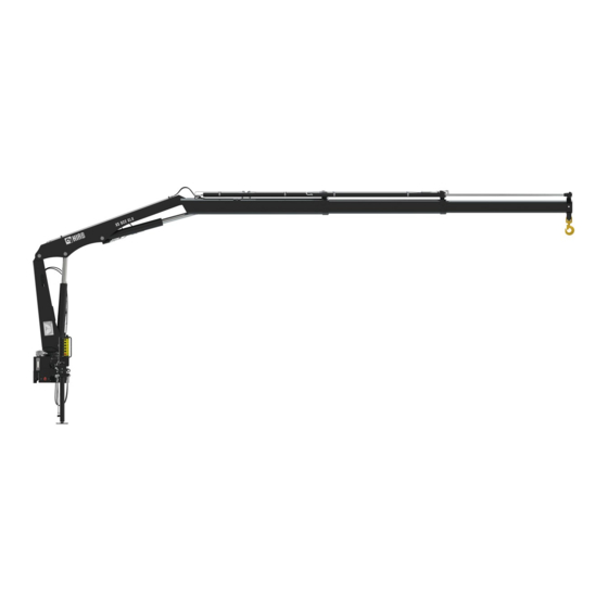
Structure and parts of the HIAB crane Boom system with hoist ① The boom system consists of the following components: • ① 1st boom • ② Hydraulic extensions The length of the hydraulic extension depends on the type of crane. -
Page 14: Stabiliser Leg System
Separate lifting accessories, help to make or use a slinging device: eye-hooks, shackles, eye-bolts etc. Stabiliser leg system Every truck mounted HIAB crane has a minimum of one stabiliser leg. Auxiliary stabilisers may be needed for heavy cranes. • Stabiliser beam ①... -
Page 15: Operating System - Hydraulic Components
Structure and parts of the HIAB crane Operating system - hydraulic components The operating system consists of the following hydraulic components: • oil tank • hydraulic pump PTO or a 12V/24V motor • Main control valve • hydraulic hoses and pipes •... -
Page 16: Description Of Hiab T-Hiduo 013/018/023/029/038
The cranes are supplied in versions from: HIAB T-HiDuo 013-1 (reach 2 metres) to HIAB T-HiDuo 013-3 (reach 4,2 metres) Note! VSL is not available on Hiab T-HiDuo 013 HIAB T-HiDuo 018-1 (reach 2 metres) to HIAB T-HiDuo 018-3 (reach 4,2 metres) -
Page 17: Safety Precautions And Warnings
Safety precautions and warnings Operating conditions You may only use the crane under the following conditions: • In the open air, or in spaces with sufficient ventilation. DANGER • If you use the crane in a confined space you could suffocate from the exhaust gases from the vehicle. -
Page 18: Definition Of A Hiab Loader Crane
Definition of a HIAB loader crane Usage of the crane The HIAB loader crane is used to lift and move loads in the working area permitted by the load plate and the load diagram. The cranes are normally mounted on a vehicle but they can also be mounted on a fixed base plate. -
Page 19: Noise Declaration
Safety precautions and warnings 3.2.1 • Continuous use as a production crane in assembly lines, foundries…, except for cranes prepared for that purpose • Loading cargo that is partially loaded or fastened by other means, without making sure the capacity of the crane is enough for the entire load •... -
Page 20: Warning Signs
Safety precautions and warnings 3.2.2 3.2.2 Warning signs xxxx xxxx xxx xxxx 1820 1065 LOADER CRANE CARGOTEC POLAND SP. Z 0.0. METALOWA 2 73-102 STARGARD SZCZECINSKI POLAND 187-5931/2 3.2.3 Maximum load Lifting capacity Your crane has a certain lifting capacity, ex- pressed in kNm or tm. - Page 21 Safety precautions and warnings 3.2.3 DANGER • Overloading could result in damage to the crane or in the worst case, personal injury or death • Never increase a hanging load, since that may cause a load holding valve to open and/or the vehicle to turn over.
- Page 22 Safety precautions and warnings 3.2.3 Load diagram The load diagrams are placed on the column and show the maximum loads your crane may lift in the entire working zone (manual extensions ex- cluded). The load diagram drawing will also be found in the enclosed Technical Data.
-
Page 23: Maximum Load Moment
Safety precautions and warnings 3.2.4 3.2.4 Maximum load moment If your crane has reached the maximum load moment (lifting capacity), the OLP gives a warning and locks any crane movement that will increase the load moment. This is known as an OLP situation. - Page 24 Safety precautions and warnings 3.2.4 Lifting the load You obtain the best from your crane in this way: Ensure that you always have the work in clear view. If you cannot see the load properly, you could cause a fatal accident or serious damage. Sling length Always attach the load using the shortest possible sling.
-
Page 25: Determination - Hoist
Safety precautions and warnings 3.2.6 Make smooth crane movements: operate the crane with various functions simultaneously. In this way you will also prevent the hydraulic system heating up quickly. DANGER Never exceed the maximum permissible load- ing of the hook. 3.2.6 Determination - Hoist The TC hoists belong to the group of hoisting winches. - Page 26 Safety precautions and warnings Lift Raised arm and index finger raised. Circular motion with hand. Lower Arm pointing downwards and index finger down. Circular motion with hand. Stop all crane movements Also: Hold the load in position. Raise the open hand, with the palm clearly visible, and arm at shoulder height.
- Page 27 Safety precautions and warnings Very short movement Place the hands a very short distance apart, with the palms facing each other. The hands may be held either horizontally or vertically. The next movement may be: Lift, lower, move the lifting gear, change the reach, or turn.
-
Page 28: Wind Speeds
Safety precautions and warnings Wind speeds Wind speed averaged over 10 minutes at a height of 10 m Above flat ground Characteristics Wind Force Wind type Calm Calm, smoke rises vertically or nearly 0.0 - 0.2 vertically Slight breeze Wind direction recognisable from smoke plumes, the wind begins to be 0.3 - 1.5 noticeable on the face;... -
Page 29: Use Of The Crane
Safety precautions and warnings Use of the crane Starting crane operation DANGER • Wear a safety helmet (compulsory in some countries!). • Check that the ground is sufficiently flat and firm. • To ensure that the vehicle stays in its position, always engage the parking brake and place chocks under the wheels. - Page 30 Safety precautions and warnings DANGER • Do not stand in front of the hydraulically operated stabiliser legs when you are oper- ating them! • Never use the stabiliser legs as a parking brake, since the vehicle could start to slide. •...
-
Page 31: Preparations For Use
Safety precautions and warnings 3.5.1 DANGER Do not stand in front of the boom system when operating the crane out of parking position. 3.5.1 Preparations for use DANGER Ensure that there are no unauthorised persons within the operating range of your crane! Mark out the working range, e.g. - Page 32 Safety precautions and warnings 3.5.1 DANGER • If a part of the crane comes in contact with an electricity line, you will be electro- cuted! • Maintain the following minimum distances between the crane and overhead electricity lines, unless otherwise prescribed by na- tional rules.
- Page 33 Safety precautions and warnings 3.5.1 DANGER • Keep checking that there are no unauthor- ised persons within the operating reach of the crane! • Make certain that you can always see the load! If your view of the load is not adequate, have someone else give you signals.
- Page 34 Safety precautions and warnings 3.5.1 WARNING • Never push a load along the ground, or the vehicle's load space, with the extension boom. This can cause damage to the boom system. This will lead to expensive repairs. • Never use the extension boom as a jack. This could damage the slewing bearings and the connection between the crane column and the crane base.
-
Page 35: Ending Crane Operation
Safety precautions and warnings 3.5.4 Driving with the crane DANGER • Never drive the vehicle if there is a load suspended from the crane. • Before you move the vehicle: Check that there is no pump flow to the crane control valve. The PTO or power supply must be disengaged. -
Page 36: Use Of The Hoist
Safety precautions and warnings Use of the Hoist The hoist is a crane accessory which permits load handling without any or only limited boom movement. Lifting and lowering is achieved by wind- ing/unwinding the drum rope. During hoist operation, the rope must not be pulled off the hoist drum completely. - Page 37 Safety precautions and warnings WARNING Make sure that ropes do not touch or slide over corners, cutting edges or other obsta- cles, for example sharp edges on surfaces close to the wire rope. The swing is mainly caused by the wind and can occur with or without load.
-
Page 38: Use Of Lifting Equipment
Safety precautions and warnings Use of lifting equipment DANGER • Only use lifting accessories that are suit- able for your crane. Contact a HIAB service workshop. • Never attempt to install add-on lifting accessories yourself! • Add-on lifting accessories may only be installed by an authorised HIAB service workshop. - Page 39 Safety precautions and warnings WARNING Take care when mounting/demounting the crane on/off the vehicle. Roughly handling can seriously damage the crane or the vehicle. Operator's Manual GB...
-
Page 40: The Safety System
If you do not use the system for 30 minutes, it will switch itself off, in order to prevent draining the truck battery. This feature can be cancelled. Contact your HIAB service workshop. How the safety system works On the crane there are various sensors and indicators which send signals about the crane’s... -
Page 41: Components Of The Space 4000 Safety System
When the fault is serious, use of the crane is blocked completely. DANGER Never try to repair the control system yourself. Repairs may only be made by a HIAB service workshop! Components of the SPACE 4000 Safety System Control valve ①... -
Page 42: Operating Components
The Safety system Dump valve 1 ③ ③ • To prevent high pressure and thereby unnec- essary heating of the oil there is an automatic dumping function. When no lever movement has been made for 3 seconds SPACE system opens the dump valve 1 and the oil is returned directly to the hydraulic tank. -
Page 43: Main Control Valve
The Safety system Main control valve The speed of a function corresponds to the extent of the lever movement, as long as the oil flow is sufficient. When the oil flow is insufficient, one or more functions will stop. Control valve lever function Slewing ①... -
Page 44: User Panel Space 4000
The Safety system User panel SPACE 4000 Functions: Buttons 1-7 • Button ①. To switch the safety system on and off. • Button ② Not active in this configuration. • Button ③. For OLP release if the crane is in an OLP situation and for disconnecting the automatic ①... -
Page 45: Indicator Leds On User Panel, Space 4000
The Safety system Indicator LEDs on user panel, SPACE 4000 ⑭ Power on/off Green light on: The system is on. Green light flashing: System on and the stop button has been pressed. Red light flashing: CAN communication has been lost. Stabiliser extension Not active in this configuration. -
Page 46: Xsdrive Lite Controller
The Safety system Dump valve Blue light on: Dump activated. Blue light on: Crane has enhanced capacity (ADC mode). Hoist Green light on: Hoist mode. Red light flashing: 90% of OLP pressure. Red light on: 100% of OLP pressure. VSL-OLP reached. Stabiliser legs Green light on: Stabiliser leg set. - Page 47 The Safety system The controller has: 4 Levers for proportional functions programmed according to the item Menu selection. ① Menu selection Press to toggle between menus 1 to 4. ② Press and hold the button whilst operating a pressure OLP release reducing function.
-
Page 48: Indicator Led's On Xsdrive Lite Controller
The Safety system Indicator LED's on XSDrive Lite controller The indicator LEDs on the controller indicates button positions, errors, stability, cylinder pres- sure, hoist etc. ① Battery Red light on: Low power ② Service Red light on: Error detected in the system ③... -
Page 49: Remote Control Xsdrive Lite With Radio
The Safety system 4.10 4.10 Remote control XSDrive Lite with radio The radio consists of: • Transmitter, fitted in the controller • Receiver, fitted on the operating base. Each transmitter is programmed to only func- tion with its own receiver. When there is interference with the transmission, it is pos- sible to change the channel. -
Page 50: Battery Charger Xsdrive Lite
The Safety system 4.11 4.11 Battery charger XSDrive Lite The battery charger is to be fitted in a protected environment. Lamp ① is lit continuously when the battery charger is ready for use. Place the battery in the charger. Lamp ② flashes slowly during precharging. When lamp ②... -
Page 51: Locking And Unlocking The Controller
The Safety system 4.13 Menu 1 Slewing, first boom, extension boom, (hoist) Menu 2 Stabiliser legs Menu 3 [option] Slewing, attachment. (If crane is equipped with remote controlled stabiliser): left and right stabiliser extension, left and right stabiliser leg. [option] Similar to menu 3 but for extra stabiliser legs Menu 4 4.13 Locking and unlocking the con- troller... -
Page 52: Functions In Xsdrive Lite
The Safety system 4.14 4.14 Functions in XSDrive Lite The system provides a large number of functions. Certain functions are standard, others are options. Controlling the crane speed At start up, the system by default is set to full speed. To reduce the speed, push button once. - Page 53 The Safety system 4.14 VSL Variable Stability Limit The VSL function detects the position of the stabiliser extensions and that the stabiliser legs are pressed to the ground. This optimize the crane lifting capacity in relation to the vehicle's stabil- ity.
-
Page 54: Starting Crane Operation
Starting crane operation Starting operations Placing the vehicle • General case: 0° Place the vehicle on a flat and firm surface. The vehicle inclination during crane operation must not be more than allowed in the Technical 3° 5° Data for your crane. To determine the inclination of the truck, check the spirit level on the crane. - Page 55 Starting crane operation Power Pack [option] The power for the Power Pack comes from the truck battery. When the crane is operated for a longer period the battery could run flat. To prevent this keep the truck engine running. Start the safety system The operating levers must be in the neutral position before start up.
-
Page 56: Extend Stabiliser Extensions And Set Stabiliser Legs
Starting crane operation The warning lamps on the stabiliser legs blink swell light. Extend stabiliser extensions and set stabiliser legs To ensure the full crane capacity and stability, all the stabiliser extensions and legs must be fully extended and set to the ground without lifting the wheels off the ground. - Page 57 Starting crane operation Manual controlled stabiliser extension and leg Unlock the catcher ① and the handle ②. Extend the stabiliser extension and lock with the handle ② Place the leg on the ground: 1. Remove the locking pin ③ and place it in one of the holes to get a suitable height.
- Page 58 Starting crane operation Manual controlled stabiliser extension and tilt- able stabiliser leg 1. Unlock the catcher ① and the handle ②. Extend the stabiliser extension a little, until the stabiliser leg can be rotated free of the vehicle. 2. Be careful when tilting the stabiliser leg from transport position: Unlock the stabilis- er leg with the handle ③...
-
Page 59: Operate The Crane Out Of Parked Position
Starting crane operation Operate the crane out of parked position 1. Raise the first boom. 2. Slew the crane to working position.The crane is ready for use. ! NOTE As soon as you have selected remote control operation, it is impossible to operate the main control valve levers. -
Page 60: During Operation
During operation OLP (Overload protection) OLP (Overload protection) The OLP function is a safety function in SPACE that prevents overloading of the crane. On the boom system: With 90% of maximum permitted load, a prewarning is given. The warn- ing lamp on the stabiliser leg double blinks and the cylinder pressure LEDs flash red. -
Page 61: Manual Extensions [Option]
During operation OLP Release In certain OLP situations, the first and second booms can be locked. It is then possible to release the OLP for approximately 5 seconds. To release the OLP Press the button , while moving one lever. There is a waiting time before the release opera- tion can be activated again. - Page 62 During operation • Always extend the hydraulic extensions first, then the manual extensions. • The use of manual extensions should be restricted to the longest outreach needed. When this reach is not needed, the manual extension should be retracted. DANGER Do not stand in front of moving parts.
- Page 63 During operation 3. Turn the locking device 90 degrees clock- wise and pull it out. 4. Retract the manual extension fully by hand and secure it by turning the locking device back. DANGER • Make sure that the locking device is properly locked.
-
Page 64: Change From Hoist To Hook Operation
Change from hoist to hook operation Change from hoist to hook oper- ation The hoist should be in horizontal position. 1. Unwind the rope until the counterweight touch the ground and rope is without tension. 2. Detach the sheave block ① from its bracket and the block bracket ②... - Page 65 Change from hoist to hook operation 6. Wind the rope until the counterweight is about 30 cm from the role ③. 7. Attach the shekel to the loop at the edge of the hoist. 8. Wind the rope until it settles on the roll with slight tension.
-
Page 66: Ending Crane Operation
Ending crane operation Operate the crane to parking position DANGER When parking the crane, slew the boom away from driving position to avoid injury. 1. Retract the extensions completely. 2. Fold in the hook. 3. Lower the first boom to parking position. Placing the stabiliser legs in the transport position Activate stabiliser leg operation. - Page 67 Ending crane operation Manual controlled stabiliser extension and leg 1. Turn the handle ④ upwards and remove the locking pin ③. 2. Rise the leg and lock it with the locking pin ③. 3. Unlock the handle ② and retract the stabi- liser extension.
-
Page 68: Switching Off The Safety System
Ending crane operation Manual controlled stabiliser extension and tilt- able stabiliser leg 1. Raise the stabiliser leg completely. 2. Unlock the stabiliser leg with the handle ③ and rotate the leg manually. 3. Lock the stabiliser leg with the handle ③. 4. -
Page 69: Emergency Operation Main Control Valve
To operate the crane like this is HIGHLY DANGEROUS because during emergency op- eration all crane security is disconnected. Always go to/contact a HIAB service work- shop when the seal wire has been broken. 1. Break the security sealing on the dump valve. - Page 70 Ending crane operation • A warning, visible and audible from the driving position for transport, indicates when the crane height exceeds a predetermined maximum and when the manual operated stabiliser extensions/tiltable stabiliser legs are not locked in the transport position. •...
-
Page 71: Maintenance And Service
Welding work on the crane may only be carried out by, or in close consul- tation with, a HIAB service workshop. • Do not drill into the crane yourself. Drill- ing work on the crane may only be carried out by, or in close consultation with, a HIAB service workshop. -
Page 72: Warranty
Determine if you can still park the crane. If you can: park the crane and go to a HIAB service workshop. If you cannot: contact a HIAB service workshop. 6. In all other cases, contact a HIAB service workshop. Warranty HIAB only provides a warranty if: •... -
Page 73: Follow The Maintenance Instructions
• All security seal wires on the valves are still intact. Always use original HIAB parts and tools. Follow the maintenance instruc- tions! Take the crane, at least once a year, to a HIAB service workshop for inspection and mainte- nance. Maintain lifting accessories according to the supplier’s instructions. - Page 74 (switch off drive motor). Checking time approx. 5 minutes. The load must not sink in this condition. If the load sinks, stop the operation and have the fault rectified by a HIAB service workshop. • Inspect the braking system. Operator's Manual GB...
-
Page 75: Daily Inspection
• Check that the plane bearing ⑤ or the swivel ⑥ are in good conditions. DANGER In the event of damage or worn that prevents a safety risk: • Do not use the hook. • Have the damage repaired immediately by a HIAB service workshop. Operator's Manual GB... - Page 76 • Check for damage to the crane structure (e.g. any formation of cracks). DANGER In the event of damage that presents a safety risk: • Do not use the crane. • Have the damage repaired immediately by a HIAB service workshop. Operator's Manual GB...
-
Page 77: Monthly Inspection And Maintenance
Maintenance and Service 9.3.2 Hydraulic system • Check that there are no leaks from the hydraulic hoses, lines and connections. • Check oil level in the tank. If necessary, fill to correct level. ! NOTE Always place the vehicle on level ground with the crane in transport position while checking the oil. - Page 78 Maintenance and Service 9.3.2 Bolts and screw fixings • Check that bolt and screw fixings are tight- ened. Cables and sensors • Check that these are in good condition. Lubrication schedule • Carry out the lubrication according to the instructions. Hydraulic system •...
-
Page 79: Annual Maintenance
Maintenance and Service 9.3.3 9.3.3 Annual maintenance Take the crane, at least once a year, to a HIAB service workshop for inspection and maintenance. Carry out the following maintenance at least once a year. Hydraulic oil • Change the hydraulic oil. -
Page 80: Check Rope
Maintenance and Service 9.3.4 9.3.4 Check rope WARNING As ropes undergo very heavy strain and are not of permanent durability, it is important for the safety of the hoist system and like this for their operating personnel, to carry out a thorough check-up and to renew the rope in time. -
Page 81: Requirements Of The Rope
Do not clean the rope with steam jet blower or high pressure cleaner. 9.3.6 Requirements of the rope Rope requirements For the hoists we recommend a rotating resistant rope, cross lay to the right. Always use HIAB original rope. possible hoisting force (kN) hoist type rope Ø (mm) -
Page 82: Change Of Rope
Maintenance and Service 9.3.7 9.3.7 Change of rope WARNING • Incorrect installation of the rope may allow the load to drop down, causing material damage, severe injury or even death. • Always wear protective gloves when han- dling a hoist rope. •... - Page 83 Maintenance and Service 9.3.7 • or place it on the floor in an eight-shaped figure (a left turn followed by a right turn, etc.) to prevent loops and tangling. Hoist rope end mounting. 1. Locating pins (2x) 2. Mounting screws (4x) 3.
-
Page 84: Lubrication
Maintenance and Service e. Remove the two pins that held the spring arms of the pressure roller (placed during removal of the rope). f. Spool the rope onto the drum. Keep the hoist rope tensioned and check that the rope does not tangle and loop. -
Page 85: Lubrication Schedule
Maintenance and Service 9.4.1 9.4.1 Lubrication schedule Lubricate after every 16 hours of use. SG 02.94 p/n 55135. Lubricate after every 50 hours of use. Lubricate after every 50 hours of use. If the loader is not to be used for some time all points should be lubricated. -
Page 86: Lubrication Of The Column Bearings
Maintenance and Service 9.4.2 9.4.2 Lubrication of the column bear- ings DANGER The column bearings must be lubricated while the crane is slewed. If one person lubricates the column bearings, while another is slewing the crane: Take care that the person lubricating the bearings does not come into contact or get crushed by the crane! If you are lubricating the column bearings... -
Page 87: Checking The Oil Tank Level
Maintenance and Service 9.5.2 Make sure that the area around the filter is clean to prevent contamination of the hydraulic oil. 1. Switch off the hydraulic system and release the filter of pressure. 2. Clean the immediate surrounding area of the filter. - Page 88 Filling the oil tank with hydraulic oil The oil used for filling must be clean. Do not mix different oils. Hydraulic oil that is approved for HIAB products must comply with one of the following standards or equivalents: -DIN 51524 part 3...
- Page 89 When changing from mineral oil to a non- polluting synthetic oil, or when changing to biodegradadle oil, contact a HIAB service work- shop. Viscosity of oil The viscosity of the oil is of great importance to achieve high efficiency of the hydraulic system.
-
Page 90: Hoist Gear, Top Up Or Exchange Oil
Maintenance and Service 9.5.4 After filling the tank 1. Operate each crane function to its end positions. 2. Operate the crane to parking position. 3. Check and top up the oil tank to max level on the tank gauge. 4. Bleed the system. 9.5.4 Hoist gear, top up or exchange NOTE: To remove any oil inside the reduction gear, it must be stored in appropriate containers... -
Page 91: Bleeding Air From The Hydraulic System
Maintenance and Service 9.5.5 Lubricant must be changed the first time within and not later than 50/60 hours from running in. In normal environmental conditions, lubricant can be renewed every 500 hours of work. For recommended lubricants see 1.3 Specifications of consumables. - Page 92 Maintenance and Service 9.5.5 • after working on the hydraulic system • if your crane works slowly or jerkily • if your crane has not been used for a long time WARNING Air in the hydraulic system can lead to faults and damage To bleed air from the hydraulic system, pro- ceed as follows:...
-
Page 93: Troubleshooting
Maintenance and Service Troubleshooting 9.6.1 Main fuses If the microprocessor detects a fault, this must be rectified immediately. Fault Probable cause Action The control system does not Defective fuses 1. Replace faulty fuses work at all in the: The indicator light next to - vehicle On/Off button on the user - standard box... -
Page 94: Faults On The Crane
• Only correct yourself the faults that ac- cording to the table you may rectify. • Follow the instructions exactly! • All other faults must be corrected by personnel in a HIAB service workshop! Fault Probable cause Action The hydraulic pump makes... - Page 95 Maintenance and Service 9.6.2 External Display [option] Placing The unit shall be placed under the plastic cover together with the SPACE-box where it is pro- tected from direct water splash. Start up The External display automatically starts when the SPACE system is started. Operating modes The display has three basic operating modes: 1.
-
Page 96: Faults In The Hoist
• Only correct yourself the faults that ac- cording to the table you may rectify. • Follow the instructions exactly! • All other faults may be dealt with only by personnel in a HIAB service workshop! Symptom Probable cause Action... - Page 97 Verify hydraulic system speed. supply volume. supply volume and correct as required. Damaged hoist motor. Go to a HIAB service work- shop to have the motor re- placed. Hoist center line is distorted Contact a HIAB service due to uneven mounting sur- workshop.
-
Page 98: Decommissioning
Decommissioning 10.1 Decommissioning a crane Cranes are designed and manufactured taking the environment into consideration. Environmental requirements and soundness have been considered when selecting the raw materials. The metal parts are designed to achieve a light and durable construction, this includes the selection of higher- quality grades of steel. - Page 99 Decommissioning 10.1 Unsorted waste should be delivered to a landfill • drained hydraulic hoses, electrical wires, con- trol cables, seat, hydraulic cylinder seals, lights, small plastic and rubber parts. Hazardous waste is delivered to a collection point for hazardous waste •...
-
Page 100: Technical Data
Technical Data 11.1 Load plate table The Installer must fill in the valid meters (m) and kilos (kg) in this table, following instructions given in the Installation instructions. The enclosed Technical Data must be stored together with this Operator’s manual. Operator's Manual GB...
Need help?
Do you have a question about the HIAB T-HiDuo 013 CE and is the answer not in the manual?
Questions and answers