Table of Contents
Advertisement
Quick Links
Please note that Cypress is an Infineon Technologies Company.
The document following this cover page is marked as "Cypress" document as this is the
company that originally developed the product. Please note that Infineon will continue
to offer the product to new and existing customers as part of the Infineon product
portfolio.
Continuity of document content
The fact that Infineon offers the following product as part of the Infineon product
portfolio does not lead to any changes to this document. Future revisions will occur
when appropriate, and any changes will be set out on the document history page.
Continuity of ordering part numbers
Infineon continues to support existing part numbers. Please continue to use the
ordering part numbers listed in the datasheet for ordering.
www.infineon.com
Advertisement
Table of Contents

Related Manuals for Cypress FM3 MB9B100A Series


Summary of Contents for Cypress FM3 MB9B100A Series
- Page 1 Please note that Cypress is an Infineon Technologies Company. The document following this cover page is marked as “Cypress” document as this is the company that originally developed the product. Please note that Infineon will continue to offer the product to new and existing customers as part of the Infineon product portfolio.
- Page 2 THIS SPEC IS OBSOLETE Spec No: 002-04371 Spec Title: AN7204371-FM3 MB9B100A/300A/400A/500A Series Microcontroller Inverter Reference Board Replaced by: NONE...
-
Page 3: Table Of Contents
AN7204371 FM3 MB9B100A/300A/400A/500A Series Microcontroller Inverter Reference Board This book provides the detail hardware information of the Inverter reference Board with Cypress’s FM3 family. Contents Preface ..............1 Setup the USB-to-UART connection....15 About this manual ..........1 Hardware ..............16 Related document ............ -
Page 4: Introduction
Introduction Overview The Inverter Reference Board with Cypress’s FM3 family is intended to aid the user in the rapid evaluation and development of motor control applications using MB9B500 Series MCU which are embedded with ARM Cotex-M3 CPU core. This reference board is targeted to control Permanent Magnet Synchronous Motors in sensor-less operation. -
Page 5: Features
SPI communication port (J10). UART communication port (J9). Programming and debug interface: JTAG via 20- pin port (J3). Serial programming port: Serial programming port (J1). Additional Protection Circuitry: 250 VAC/15A fuse In-rush current limiter www.cypress.com Document No. 002-04371 Rev.*A... -
Page 6: Getting Start
DC-Link Board can make smoothly 100Hz half-sine-wave power and it can provide to DC bus through three electrolytic capacitors. The input and output cables should be with the minimum current rating of 10A. Figure2-1 shows the connection of the boards. Figure 2. Connection of the Boards www.cypress.com Document No. 002-04371 Rev.*A... -
Page 7: Connectors Of System
Description N input of AC mains L input of AC mains Earth Ground L output of filtered AC mains N output of filtered AC mains 15V_C,5V_C output 5V_A output J3,J4 Power supply for cooling fans www.cypress.com Document No. 002-04371 Rev.*A... - Page 8 Figure 4. Connectors on DC-Link Board Table 2-2 collects the definition of the connectors on DC-Link board. Table 2. Definition of Connectors on DC-Link Board Number Port Designator Description PFC positive input DC bus positive output www.cypress.com Document No. 002-04371 Rev.*A...
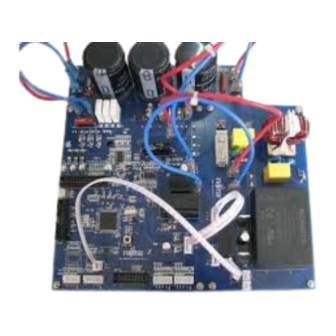
- Page 9 C o n n e c t o r s o n I n ve r t e r B o a r d The connectors on Inverter board are shown in Figure2-4. Figure 5. Connectors on Inverter Board www.cypress.com Document No. 002-04371 Rev.*A...
- Page 10 DC bus positive input(to P3 on DC-Link board) GND(to P4 on DC-Link board) Serial programming port MFT1 port JTAG port 5V_A input 15V_C,5V_C input MFT2 port 18,19 J7,J8 Quadrature Position/Revolution counter interfaces Isolated SPI port Isolated UART port www.cypress.com Document No. 002-04371 Rev.*A...
- Page 11 IAR system tools including the emulator and complier since our project is developed with IAR system tools. Figure 2-4 shows the connection between the reference systems with J-link. Figure 6. JTAG Connection with IAR JTAG tool www.cypress.com Document No. 002-04371 Rev.*A...
- Page 12 Note: Make sure that the computer or reference board is connected to isolated AC mains supply before connecting the reference system with the J-link or host computer. Figure Connection between inverter board compressor (For example, U is red line, V is black line, and W is blue line.) www.cypress.com Document No. 002-04371 Rev.*A...
-
Page 13: Debug The System
Debug the System Before debugging, the IAR EWARM must be installed. The firmware is developed with it. How to prepare for debugging, please refer as follows: Open the target project. Figure 7. View of Project www.cypress.com Document No. 002-04371 Rev.*A... - Page 14 FM3 MB9B100A/300A/400A/500A Series Microcontroller Inverter Reference Board Click right button on the project name, and select rebuild all. The project will be rebuilt. Figure 8. Rebuild the Project www.cypress.com Document No. 002-04371 Rev.*A...
-
Page 15: Flash Programming Using Uart
2. Connect the jumper JP3 that keeps the MD0 ‘H’. 3. Push SW2 to keep the P60 ‘L level’. 4. Power on the reference board and reset the MCU by pressing the SW1. 5. Programming the flash using CYPRESS FLASH MCU Programmer for FM3. www.cypress.com Document No. 002-04371 Rev.*A... -
Page 16: Motor Control Gui
This chapter will introduce the GUI Software Overview Cypress provides a computer-based interface for this reference board. The GUI provides a wide range of control functions for motor operations. Not only can user set the speed and rotation direction, but only can observe the value of constants and variables, or configure the key parameter of the system. -
Page 17: Setup The Usb-To-Uart Connection
The reference board provides an isolated UART port to communicate with a USB-to-UART board. This board is connected to the PC through USB port. In order to ensure the communication, it is recommended shorting the length of wires. The user can connect the communication kit as below: www.cypress.com Document No. 002-04371 Rev.*A... -
Page 18: Hardware
R1 -- The resistor that is used to discharge the C1 and C4 safely. These three components make common noise filter. C2, C3 are Y capacitors. C1, C4 -- Film capacitors to aid in the suppression of EMI. www.cypress.com Document No. 002-04371 Rev.*A... -
Page 19: In-Rush Limiter
Rectified input current is measured using the shunt resistor R17 and the amplifier U4C unit. The gain of amplifier is set at 5. Rectified input voltage zero-crossing event is sensed using a voltage divider (R21, R22) and an opt-coupler (U3). www.cypress.com Document No. 002-04371 Rev.*A... -
Page 20: 3- Phase Invert Stage
At the same time the module will output low level from VFO pin. A pull-up resister is need on VFO pin because it is open-collector type. If you want to know more detail, please refer to the each device’s datasheet. www.cypress.com Document No. 002-04371 Rev.*A... - Page 21 2.5V. One channel of voltage is higher than 4.75V DC. The U6D will output a high level up to 13.5V to the power module. This fault signal can turn the low side IGBTs off. The threshold of the phase over-current protection can set 15A as default value. www.cypress.com Document No. 002-04371 Rev.*A...
-
Page 22: Mft1 And Mft2 Ports
V_AC Rectified AC voltage PFC_RTH Temperature of PFC module GND_C Digital GND Zero Check Zero-crossing event detection PRT_DC Over-voltage protection VFO_PFC Fault signal from PFC module PWM_PFC PWM signal to PFC module NULL not connected www.cypress.com Document No. 002-04371 Rev.*A... -
Page 23: Isolated Ports
The SW2 is used to shift the level on P60, as well as JMP3 is used to shift the level on MD0. When P60 = 0 and MD0 = 1, the programming is allowed, or it is disabled. www.cypress.com Document No. 002-04371 Rev.*A... -
Page 24: Appendix
FM3 MB9B100A/300A/400A/500A Series Microcontroller Inverter Reference Board Appendix Schematic 7 . 1 . 1 P o w e r B o a r d Figure 13. Power Board www.cypress.com Document No. 002-04371 Rev.*A... - Page 25 FM3 MB9B100A/300A/400A/500A Series Microcontroller Inverter Reference Board 7 . 1 . 2 I n ve r t e r B o a r d Figure 14. PFC stage www.cypress.com Document No. 002-04371 Rev.*A...
- Page 26 FM3 MB9B100A/300A/400A/500A Series Microcontroller Inverter Reference Board Figure 15. Inverter Stage www.cypress.com Document No. 002-04371 Rev.*A...
- Page 27 FM3 MB9B100A/300A/400A/500A Series Microcontroller Inverter Reference Board Figure 16. MCU system www.cypress.com Document No. 002-04371 Rev.*A...
- Page 28 FM3 MB9B100A/300A/400A/500A Series Microcontroller Inverter Reference Board Figure 17. Connectors www.cypress.com Document No. 002-04371 Rev.*A...
- Page 29 FM3 MB9B100A/300A/400A/500A Series Microcontroller Inverter Reference Board 7 . 1 . 3 D C - L i n k B o a r d Figure 18. DC-Link Board www.cypress.com Document No. 002-04371 Rev.*A...
-
Page 30: Document History
Document Title: AN7204371 - FM3 MB9B100A/300A/400A/500A Series Microcontroller Inverter Reference Board Document Number: 002-04371 Revision Orig. of Submission Description of Change Change Date CBZH 07/13/2011 Initial release 5029057 CBZH 02/12/2016 Migrated Spansion Application Note AN706-00042-1v0-E to Cypress format Document Obsoleted www.cypress.com Document No. 002-04371 Rev.*A... - Page 31 Cypress Source Code and derivative works for the sole purpose of creating custom software and or firmware in support of licensee product to be used only in conjunction with a Cypress integrated circuit as specified in the applicable agreement.
Need help?
Do you have a question about the FM3 MB9B100A Series and is the answer not in the manual?
Questions and answers