Table of Contents
Advertisement
Please note that Cypress is an Infineon Technologies Company.
The document following this cover page is marked as "Cypress" document as this is the
company that originally developed the product. Please note that Infineon will continue
to offer the product to new and existing customers as part of the Infineon product
portfolio.
Continuity of document content
The fact that Infineon offers the following product as part of the Infineon product
portfolio does not lead to any changes to this document. Future revisions will occur
when appropriate, and any changes will be set out on the document history page.
Continuity of ordering part numbers
Infineon continues to support existing part numbers. Please continue to use the
ordering part numbers listed in the datasheet for ordering.
www.infineon.com
Advertisement
Table of Contents

Related Manuals for Cypress Traveo II


Summary of Contents for Cypress Traveo II
- Page 1 Please note that Cypress is an Infineon Technologies Company. The document following this cover page is marked as “Cypress” document as this is the company that originally developed the product. Please note that Infineon will continue to offer the product to new and existing customers as part of the Infineon product portfolio.
- Page 2 Traveo II Starter Kit User Guide Traveo II Starter Kit User Guide Document Number: 002-25314 Rev. *B Cypress Semiconductor An Infineon Technologies Company 198 Champion Court San Jose, CA 95134-1709 www.cypress.com www.infineon.com...
- Page 3 High-Risk Device, or to affect its safety or effectiveness. Cypress is not liable, in whole or in part, and you shall and hereby do release Cypress from any claim, damage, or other liability arising from any use of a Cypress product as a Critical Component in a High-Risk Device.
- Page 4 The following product is the target for this evaluation board. Quantity Description Part No. Traveo II Starter Kit CYTVII-B-E-1M-SK Board Size 114 x 52 (mm). Operating Temperature 0 to 40 °C. Traveo II Starter Kit User Guide, Document Number: 002-25314 Rev. *B...
- Page 5 RoHS Compliance European RoHS. Traveo II Starter Kit User Guide, Document Number: 002-25314 Rev. *B...
-
Page 6: Table Of Contents
A. Connections and Settings Traveo II Starter Kit Connections................23 A.1.1 User LED......................23 A.1.2 User SW......................23 A.1.3 RESET SW ....................23 A.1.4 MODE SW......................24 B. Schematics and Layouts Schematics ........................25 Layouts ........................36 Revision History Traveo II Starter Kit User Guide, Document Number: 002-25314 Rev. *B... -
Page 7: Introduction
Introduction This guide provides directions for using the Traveo™ II Starter Kit, which is the evaluation environment for Traveo II Body Entry devices of the Cypress Traveo II family 32-bit microcontroller. Table 1-1. Contents - Traveo ll Starter Kit Board... - Page 8 The product has no casing, so it is recommended that it be stored in the original packaging. Transporting the product may cause a damage or fault. Therefore, keep the packaging materials and use them when re-shipping the product. Traveo II Starter Kit User Guide, Document Number: 002-25314 Rev. *B...
-
Page 9: Overview
Selector USB micro Connector J2_A7 Potentiometer Selector Traveo II CYT2B Series RESET Switch Power LED USER Switch Arduino compatible Arduino compatible Arduino compatible pin header pin header pin header Traveo II Starter Kit User Guide, Document Number: 002-25314 Rev. *B... -
Page 10: Functional Overview
Switch TX/RX KitProg3 UART CYT2B75/95 Transceiver (PSoC 5LP) (Target Device) External External Reset Potentio Power LED Status LED Prog/Debug Prog/Debug Headers Switch meter (No Load) (No Load) (No Load) Traveo II Starter Kit User Guide, Document Number: 002-25314 Rev. *B... - Page 11 Arduino compati- Header 2.54-mm pitch 10 x 1 ble pin headers Header 2.54-mm pitch 18 x 2 J3: FTSH-110-01-L-DV-K Debug connector MIPI-10/20 Arm JTAG (optional) Not mounted by default Traveo II Starter Kit User Guide, Document Number: 002-25314 Rev. *B...
-
Page 12: Operation Points And Locations
The current consumption can be measured at J4. J4 is not mounted by default, and instead R24 is mounted. To measure current consumption, remove R24 and mount J4. Figure 3-1. MCU Power Supply Jumper Locations USB micro Bottom side R24, J4 Resettable Fuse Traveo II Starter Kit User Guide, Document Number: 002-25314 Rev. *B... -
Page 13: Main Clock
3-1. X1 is a 16-MHz oscillator with load capacitance. Figure 3-2. Main Clock Location Table 3-1. Main Clock Oscillator Part No. Model Number Remarks ABRACON ABM10-16.000MHZ-D30-T3 Surface-mounted 16-MHz oscillator Traveo II Starter Kit User Guide, Document Number: 002-25314 Rev. *B... -
Page 14: Switches
Figure 3-3. Switches Location Table 3-2. Switches Part No. Signal Name User Switch: Connects to P7.0 of MCU Reset Switch: System Reset Mode Switch: Connects to P1[2] of PSoC 5LP Traveo II Starter Kit User Guide, Document Number: 002-25314 Rev. *B... -
Page 15: Leds
LED 2 Power LED: Green, Power monitor LED (VBUS) LED 3 User LED: Amber, Connects to P1.4 of PSoC LED 4 User LED: Blue, Connects to P12.2 of MCU Traveo II Starter Kit User Guide, Document Number: 002-25314 Rev. *B... -
Page 16: Usb Interface Connector
Figure 3-5. USB Interface Connector Location USB micro Bottom side Table 3-4. USB Interface Connector Part No. Description Remarks USB micro connector 10118194-0001LF This connector is mounted on the bottom side Traveo II Starter Kit User Guide, Document Number: 002-25314 Rev. *B... -
Page 17: Can Fd Interface Connector
TJA1057GT Connects to P0.2 and P0.3 (CAN0_1) of MCU 1: GND Common ground 3-pin header (Screw terminal) 2: CANL CAN0_1 bus signal LOW 3: CANH CAN0_1 bus signal HIGH Traveo II Starter Kit User Guide, Document Number: 002-25314 Rev. *B... -
Page 18: Potentiometer
The potentiometer location and details are shown in Figure 3-7 Table 3-6. Figure 3-7. Potentiometer Location Table 3-6. Potentiometer Part No. Description Remarks Potentiometer 10 kΩ BOURNS 3313J-1-103E Connects to P6.0 (ADC[0]_0) of MCU Traveo II Starter Kit User Guide, Document Number: 002-25314 Rev. *B... -
Page 19: Arduino Compatible Pin Headers
Table 3-7. Arduino Compatible Pin Header 1 (J1) Signal Table 3-8. Arduino Compatible Pin Header 2 (J2) Signal A0 (P7_5) A1 (P7_4) A2 (P7_3) A3 (P6_5) A4 (P6_4) A5 (P13_2) A6 (P12_1) Traveo II Starter Kit User Guide, Document Number: 002-25314 Rev. *B... - Page 20 18 (14_1) 19 (14_0) 20 (P0_3) 21 (P0_2) Table 3-11. Arduino Compatible Pin Header 5 (J10) Signal 2 (P19_1) 3 (P19_2) 4 (P21_0) 5 (P21_1) 6 (P13_3) 7 (P13_5) Traveo II Starter Kit User Guide, Document Number: 002-25314 Rev. *B...
- Page 21 39 (P12_2) 40 (P19_0) 41 (P3_1) 42 (P5_3) 43 (P2_0) 44 (P5_0) 45 (P5_1) 46 (P5_2) 47 (P18_3) 48 (P18_4) 49 (P18_5) 50 (P6_0) 51 (P6_1) 52 (P6_2) 53 (P6_3) Traveo II Starter Kit User Guide, Document Number: 002-25314 Rev. *B...
-
Page 22: Debug Interface (Optional)
(The foot pattern is available on the bottom side) Table 3-15. MIPI-10/20 Connector Signal Signal Power Ground TCLK Ground Ground XRES Ground TRACE_CLOCK Ground TRACE_DATA_0 Ground TRACE_DATA_1 Ground TRACE_DATA_2 Ground TRACE_DATA_3 Traveo II Starter Kit User Guide, Document Number: 002-25314 Rev. *B... -
Page 23: Known Limitations
(Not mounted by nal oscillator, or purchase an offi- default) and the CAN FD cial evaluation board communication rate is 500 kbps at the maximum with Traveo II Starter Kit User Guide, Document Number: 002-25314 Rev. *B... -
Page 24: Connections And Settings
The correspondence between the RESET SW and the CYT2B75XX/CYT2B95XX device pin and the port pin as in Table A-3. Table A-3. RESET Switch CYT2B75XX/CYT2B95XX RESET Part Number Pin Name RESET SW XRES Traveo II Starter Kit User Guide, Document Number: 002-25314 Rev. *B... -
Page 25: Mode Sw
The correspondence between the MODE SW and the PSoC 5LP pin number is given in Table A-4. Table A-4. MODE Switch PSoC 5LP RESET Part Number Pin Name RESET SW P1[2] Traveo II Starter Kit User Guide, Document Number: 002-25314 Rev. *B... -
Page 26: Schematics And Layouts
Schematics and Layouts Schematics Traveo II Starter Kit User Guide, Document Number: 002-25314 Rev. *B... - Page 27 2.2 K TX/RX UART CYT2B75/95 KitProg3 Transceiver (Target Device) (PSoC 5LP) External External Reset Potentio Power LED Headers Status LED Prog/Debug Prog/Debug Switch meter (No Load) (No Load) (No Load) Traveo II Starter Kit User Guide, Document Number: 002-25314 Rev. *B...
- Page 28 60542 60542 60542 AVEN AVEN AVEN SPPD SPPD SPPD DGND DGND Date: Date: Date: Tuesday, July 21, 2020 Tuesday, July 21, 2020 Tuesday, July 21, 2020 Sheet Sheet Sheet Traveo II Starter Kit User Guide, Document Number: 002-25314 Rev. *B...
- Page 29 SWJ_SWDIO_TMS SWDIO 60542 60542 60542 AVEN AVEN AVEN SPPD SPPD SPPD Date: Date: Date: Tuesday, July 21, 2020 Tuesday, July 21, 2020 Tuesday, July 21, 2020 Sheet Sheet Sheet Traveo II Starter Kit User Guide, Document Number: 002-25314 Rev. *B...
- Page 30 P6_1/PWM_0/PWM_M_0_N/TC_0_TR0/TC_M_0_TR1/SCB4_TX/SCB4_SDA/SCB4_MOSI/LIN3_TX/ADC[0]_1 P6_2_SCB4_CLK {10} P6_2/PWM_M_1/PWM_0_N/TC_M_1_TR0/TC_0_TR1/SCB4_RTS/SCB4_SCL/SCB4_CLK/LIN3_EN/CAN0_2_TX/ADC[0]_2 P6_3_SCB4_SEL0 {10} P6_3/PWM_1/PWM_M_1_N/TC_1_TR0/TC_M_1_TR1/SCB4_CTS/SCB4_SEL0/LIN4_RX/CAN0_2_RX/CAL_SUP_NZ/ADC[0]_3 P6_4_ADC {10} P6_4/PWM_M_2/PWM_1_N/TC_M_2_TR0/TC_1_TR1/SCB4_SEL1/LIN4_TX/ADC[0]_4 P6_5_ADC {10} P6_5/PWM_2/PWM_M_2_N/TC_2_TR0/TC_M_2_TR1/SCB4_SEL2/LIN4_EN/ADC[0]_5 P7_0_ADC {4,10} P7_0/PWM_M_4/PWM_3_N/TC_M_4_TR0/TC_3_TR1/SCB5_RX/SCB5_MISO/LIN4_RX/ADC[0]_8 P7_1_SCB5_SDA {10} P7_1/PWM_15/PWM_M_4_N/TC_15_TR0/TC_M_4_TR1/SCB5_TX/SCB5_SDA/SCB5_MOSI/LIN4_TX/ADC[0]_9 P7_2_SCB5_SCL {10} P7_2/PWM_M_5/PWM_15_N/TC_M_5_TR0/TC_15_TR1/SCB5_RTS/SCB5_SCL/SCB5_CLK/LIN4_EN/ADC[0]_10 P7_3_ADC {10} P7_3/PWM_16/PWM_M_5_N/TC_16_TR0/TC_M_5_TR1/SCB5_CTS/SCB5_SEL0/ADC[0]_11 P7_4_ADC {10} P7_4/PWM_M_6/PWM_16_N/TC_M_6_TR0/TC_16_TR1/SCB5_SEL1/ADC[0]_12 CYT2B7 Traveo II Starter Kit User Guide, Document Number: 002-25314 Rev. *B...
- Page 31 P12_1/PWM_37/PWM_36_N/TC_37_TR0/TC_36_TR1/LIN6_EN/CAN0_2_RX/TRIG_IN[21]/ADC[1]_5 P12_2 {10,11} P12_2/PWM_38/PWM_37_N/TC_38_TR0/TC_37_TR1/EXT_MUX[1]_EN/LIN6_RX/ADC[1]_6 P12_3 {10} P12_3/PWM_39/PWM_38_N/TC_39_TR0/TC_38_TR1/EXT_MUX[1]_0/LIN6_TX/ADC[1]_7 P12_4 {10} P12_4/PWM_40/PWM_39_N/TC_40_TR0/TC_39_TR1/EXT_MUX[1]_1/ADC[1]_8 P13_0_SCB3_RX {10} P13_0/PWM_M_8/PWM_43_N/TC_M_8_TR0/TC_43_TR1/EXT_MUX[2]_0/SCB3_RX/SCB3_MISO/ADC[1]_12 P13_1_SCB3_TX {10} P13_1/PWM_44/PWM_M_8_N/TC_44_TR0/TC_M_8_TR1/EXT_MUX[2]_1/SCB3_TX/SCB3_SDA/SCB3_MOSI/ADC[1]_13 P13_2_ADC {10} P13_2/PWM_M_9/PWM_44_N/TC_M_9_TR0/TC_44_TR1/EXT_MUX[2]_2/SCB3_RTS/SCB3_SCL/SCB3_CLK/ADC[1]_14 P13_3 {10} P13_3/PWM_45/PWM_M_9_N/TC_45_TR0/TC_M_9_TR1/EXT_MUX[2]_EN/SCB3_CTS/SCB3_SEL0/ADC[1]_15 P13_4 {10} P13_4/PWM_M_10/PWM_45_N/TC_M_10_TR0/TC_45_TR1/SCB3_SEL1/ADC[1]_16 P13_5 {10} P13_5/PWM_46/PWM_M_10_N/TC_46_TR0/TC_M_10_TR1/SCB3_SEL2/ADC[1]_17 CYT2B7 Traveo II Starter Kit User Guide, Document Number: 002-25314 Rev. *B...
- Page 32 P17_2/PWM_59/PWM_60_N/TC_59_TR0/TC_60_TR1/PWM_H_2_N/SCB3_TX/SCB3_SDA/SCB3_MOSI P18_0_SCB1_RX {10} P18_0/PWM_M_6/PWM_M_5_N/TC_M_6_TR0/TC_M_5_TR1/PWM_H_0/SCB1_RX/SCB1_MISO/FAULT_OUT_0/ADC[2]_0 P18_1_SCB1_TX {10} P18_1/PWM_M_7/PWM_M_6_N/TC_M_7_TR0/TC_M_6_TR1/PWM_H_0_N/SCB1_TX/SCB1_SDA/SCB1_MOSI/FAULT_OUT_1/ADC[2]_1 P18_2 {10} P18_2/PWM_55/PWM_M_7_N/TC_55_TR0/TC_M_7_TR1/PWM_H_1/SCB1_RTS/SCB1_SCL/SCB1_CLK/ADC[2]_2 P18_3 {4,10} P18_3/PWM_54/PWM_55_N/TC_54_TR0/TC_55_TR1/PWM_H_1_N/SCB1_CTS/SCB1_SEL0/TRACE_CLOCK/ADC[2]_3 P18_4 {4,10} P18_4/PWM_53/PWM_54_N/TC_53_TR0/TC_54_TR1/PWM_H_2/SCB1_SEL1/TRACE_DATA_0/ADC[2]_4 P18_5 {4,10} P18_5/PWM_52/PWM_53_N/TC_52_TR0/TC_53_TR1/PWM_H_2_N/SCB1_SEL2/TRACE_DATA_1/ADC[2]_5 P18_6_ADC {4,10} P18_6/PWM_51/PWM_52_N/TC_51_TR0/TC_52_TR1/PWM_H_3/SCB1_SEL3/CAN1_2_TX/TRACE_DATA_2/ADC[2]_6 P18_7_ADC {4,10} P18_7/PWM_50/PWM_51_N/TC_50_TR0/TC_51_TR1/PWM_H_3_N/CAN1_2_RX/TRACE_DATA_3/ADC[2]_7 P19_0 {4,10} P19_0/PWM_M_3/PWM_50_N/TC_M_3_TR0/TC_50_TR1/TC_H_0_TR0/SCB2_RX/SCB2_MISO/FAULT_OUT_2 CYT2B7 Traveo II Starter Kit User Guide, Document Number: 002-25314 Rev. *B...
- Page 33 P21_5/PWM_37/PWM_38_N/TC_37_TR0/TC_38_TR1/LIN0_RX P22_0_SCB6_MISO {10} P22_0/PWM_34/PWM_35_N/TC_34_TR0/TC_35_TR1/SCB6_RX/SCB6_MISO/CAN1_1_TX/TRACE_DATA_0 P22_1_SCB6_MOSI {10} P22_1/PWM_33/PWM_34_N/TC_33_TR0/TC_34_TR1/SCB6_TX/SCB6_SDA/SCB6_MOSI/CAN1_1_RX/TRACE_DATA_1 P22_2_SCB6_SCL {10} P22_2/PWM_32/PWM_33_N/TC_32_TR0/TC_33_TR1/SCB6_RTS/SCB6_SCL/SCB6_CLK/TRACE_DATA_2 P22_3_SCB6_SEL0 {10} P22_3/PWM_31/PWM_32_N/TC_31_TR0/TC_32_TR1/SCB6_CTS/SCB6_SEL0/TRACE_DATA_3 P23_3 {10} P23_3/PWM_M_11/PWM_M_10_N/TC_M_11_TR0/TC_M_10_TR1/SCB7_CTS/SCB7_SEL0/FAULT_OUT_3/TRIG_IN[30] P23_4 {4} P23_4/PWM_25/PWM_M_11_N/TC_25_TR0/TC_M_11_TR1/SCB7_SEL1/TRIG_DBG[0]/SWJ_SWO_TDO/TRIG_IN[31] P23_5 {4} P23_5/PWM_24/PWM_25_N/TC_24_TR0/TC_25_TR1/SCB7_SEL2/SWJ_SWCLK_TCLK P23_6 {4} P23_6/PWM_23/PWM_24_N/TC_23_TR0/TC_24_TR1/SWJ_SWDIO_TMS P23_7 {4} P23_7/PWM_22/PWM_23_N/TC_22_TR0/TC_23_TR1/CAL_SUP_NZ/SWJ_SWDOE_TDI/EXT_CLK/HIBERNATE_WAKEUP[1] CYT2B7 Traveo II Starter Kit User Guide, Document Number: 002-25314 Rev. *B...
- Page 34 Approved By 60542 60542 60542 AVEN AVEN AVEN SPPD SPPD SPPD Date: Date: Date: Tuesday, July 21, 2020 Tuesday, July 21, 2020 Tuesday, July 21, 2020 Sheet Sheet Sheet Traveo II Starter Kit User Guide, Document Number: 002-25314 Rev. *B...
- Page 35 SCH Title : SCH Title : SCH Title : TraveoII_Entry_Family_Starter_Kit TraveoII_Entry_Family_Starter_Kit TraveoII_Entry_Family_Starter_Kit Page Title : Page Title : Page Title : Arduino compatible pin-headers Arduino compatible pin-headers Arduino compatible pin-headers Traveo II Starter Kit User Guide, Document Number: 002-25314 Rev. *B...
- Page 36 DGND DGND DGND DGND Potentiometer JUMPER 1X 2 TV2_VDD 0 OHM RES0603 LED4 TV2_VDD_VR P12_2_R 560 ohm {6,10} P12_2 ADC[0]_0 0805 User LED BLUE P6_0_SCB4_MISO {5,10} 3313J-1-103E DGND DGND Traveo II Starter Kit User Guide, Document Number: 002-25314 Rev. *B...
-
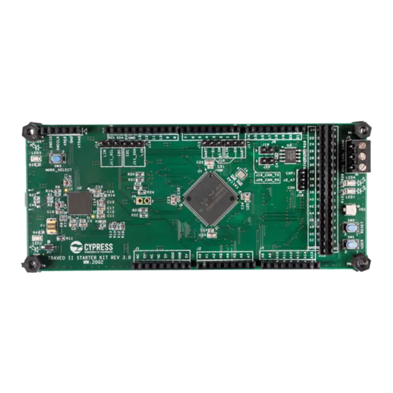
Page 37: Layouts
Figure B-11. Layout (Top View) SCL SDA STATUS LED 3 MODE_SELECT CXPI J19_CAN_TX LED4 J20_CAN_RX J2_A7 LED1 LED 2 TRAVEO II STARTER KIT REV 3.0 WW : 2002 PRIMARY ASSEMBLY Traveo II Starter Kit User Guide, Document Number: 002-25314 Rev. *B... - Page 38 Schematics and Layouts Figure B-12. Layout (Bottom View) SECONDARY ASSEMBLY Traveo II Starter Kit User Guide, Document Number: 002-25314 Rev. *B...
-
Page 39: Revision History
Replaced from “Figure B-1 to B-4” to “Figure B-1 Figure B-10”. Replaced from “Figure B-5 to B-6” to “Figure B-11 Figure B-12”. 6967760 09/18/2020 Renamed “CYTVII-B-E-1M-SK Evaluation Board” to “Traveo II Starter Kit”. Traveo II Starter Kit User Guide, Document Number: 002-25314 Rev. *B...
Need help?
Do you have a question about the Traveo II and is the answer not in the manual?
Questions and answers