
Related Manuals for FM STP 642


Summary of Contents for FM STP 642
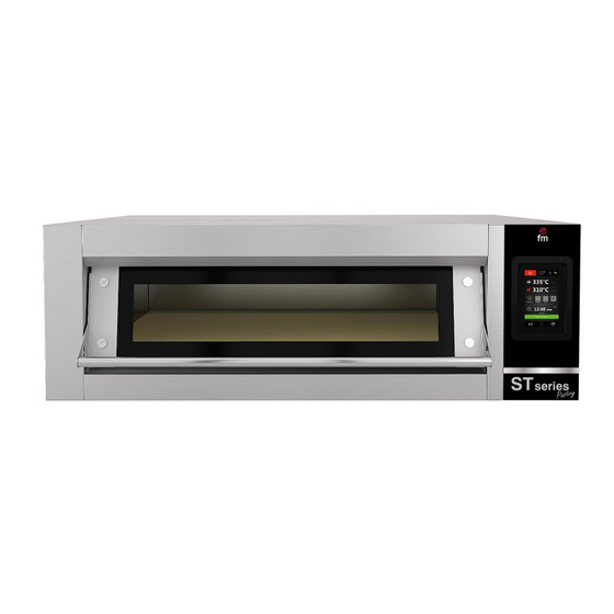
- Page 1 Instruction Manual Electric ovens Models: STP 642 (STZ 433 V5)/ STP 643 (STZ 633 V5)/ STB Module ATTENTION: Please, read these instructions before using this unit.
-
Page 3: Table Of Contents
CONTENTS CE CERTIFICATION WARRANTY GENERAL AND SAFETY STANDARDS SAFETY INSTRUCTIONS, TRANSPORT AND MAINTENANCE Unpackaging Transport Preliminary operations Placing the unit STARTING UP THE UNIT Electrical connection Water inlet (only for ovens with humidication system) Draining connection (only for ovens with humidication system) Vapour exhaust from the cooking chamber USE INSTRUCTIONS Screen. -
Page 4: Ce Certification
Type of device: HORNO / OVEN FM CALEFACCIÓN Marca / Trade.: STP 642 (STZ 433 V5) / STP 643 (STZ 633 V5) Model: MÓDULO STB We, the undersigned, hereby declare under our sole responsibility that the specified equipment is in... -
Page 5: Warranty
2. Warranty The warranty period is 12 months from the date of purchase of the unit. The warranty does not cover damages to the glass, lamps, door seals, damage to the insulating material or damage caused by improper installation or maintenance, lack of maintenance, improper repair or misuse. To process the repair of a unit under warranty or for any other query, please contact your distributor and refer to the following description table. -
Page 6: General And Safety Standards
Damages, injuries or fatal accidents could be produced due to the non-observance of the manufacturer’s indications. If the oven is installed on supports or overlaying parts, use the ones supplied by FM only and follow the assembly instructions inside the packaging. ... - Page 7 Faults caused by lime or water sediment are not included in the warranty. Failure to comply with these safety standards will release FM from any responsibility and the warranty will become null and void. Maximum loads according to the size of the units...
-
Page 8: Safety Instructions, Transport And Maintenance
The transport agency label must be clearly visible. Photographs showing the content only and exclusively will not be accepted. In either case, transport incidences should be reported to FM Industrial to manage the replacement of the machine. -
Page 9: Preliminary Operations
4.3 Preliminary operations Remove the protection film from the unit. Clean the adhesive residues with an appropriate solvent. Never use abrasive or acid products or tools that may damage the surface. If your unit is fitted with a core probe kit, remember to remove its silicon protection cap. Otherwise, it could be melted and damage the probe. - Page 10 Example of placing the unit without nearby heat sources Placing the unit next to heat sources P anel aislante ignifugo Insulating panel M in, 1 00m m M in, 700m m We recommended leaving a free working space of around 500 mm for maintenance operations. This unit is not suitable for built-in installations.
-
Page 11: Starting Up The Unit
5. Puesta en marcha del equipo To start up and install the unit appropriately, please follow the points in the “DOCUMENT FOR INSTALLING AND STARTING UP SMART UNITS”, included in the bag together with this instruction manual. Remember that any fault or breakage resulting from improper installation or starting up, will make the warranty become null and void. - Page 12 Three-phase connection 400V connected to a three-phase power socket type CETAC. MATERIAL NOT SUPPLIED THREE PHASE 230V Three phase connection 230V connected to a three-phase power socket type CETAC. MATERIAL NOT SUPPLIED In order to prevent damages from unintentional reset of the cutting thermal device, this unit should not be fed by an external control device, such as a timer, or be connected to a circuit whose supply is regularly interrupted.
-
Page 13: Water Inlet (Only For Ovens With Humidication System)
COLOUR CODE: Black (L2) Grey (L1) Brown (L3) PHASES Blue (N) NEUTRAL Yellow / Green GROUNDING 5.2 Water inlet (only for ovens with humidication system) The use of an anti-lime filter at the water supply inlet and a check valve is recommended. The oven has a ¾ connection for water inlet. - Page 14 Types of draining: 1. Wall draining: The wall draining outlet must have a vertical ventilation conduit with a diameter not smaller than 25 mm, which must be over the device top cover as shown in the image below. If there is no vertical ventilation conduit installed, proper draining is not ensured, and it may cause faults and the loss of the warranty.
- Page 15 1. Draining separated with a funnel: MATERIAL NOT SUPPLIED Floor draining: Ed.:21 – Ver.:01 – 01/01/2021...
-
Page 16: Vapour Exhaust From The Cooking Chamber
5.4 Vapour exhaust from the cooking chamber Exhaust gases may be wet and reach high temperatures. Therefore, do not use tubes made of materials not ensuring absolute thermal stability up to 250ºC to channel exhaust gases. A condenser enabling the condensation of vapours and exhaust of those vapours into a drainage may be adapted to treat cooking vapours. -
Page 17: Use Instructions
6. Use instructions______________ Attention! Read this manual thoroughly before starting the unit. 6.1 Screen. User interface and main settings 6.1.1 Switching the unit ON/OFF Please, follow this step to switch the unit on: Press the icon to activate the screen. Please, follow these steps to switch the unit off and back to standby mode: ... - Page 18 6.1.3 Setting the date and time Check that the unit is on and set at standby screen: 1. Press the icon to go to the settings menu. 2. Select “Clock” to modify the date and time. 3. Press the icon several times until the green box is on the digit you want to modify.
- Page 19 6.1.6 Injecting humidity (for ovens fitted with a humidifying system only) If your oven is fitted with a humidifying system for injecting humidity, the icon will be displayed on the screen. With this icon, injecting humidity can be activated or deactivated during the execution of the cooking cycle. When pressing this icon, all functions enabled for the humidifying system are displayed.
- Page 20 6.1.8 Internal lighting The icon switches the lighting in the internal chamber on or off. 6.1.9 Saving energy The icon activates the saving energy function, except if the fast preheating option has been selected. 6.1.10 “Expert” screen Press the “Expert” menu button to access a new screen with additional functions and information on the unit status.
-
Page 21: Setting A Recipe
6.1.11 Summary screen If no operations are made on the screen for 60 seconds, the screen changes to the summary screen mode in order to ensure higher visibility of the temperatures of resistances, and time and phase of the cooking cycle. 6.2 Setting a recipe 6.2.1 Preliminary information 1. -
Page 22: Programmed Automatic Start
6.2.3 Selecting a saved recipe Follow these steps to select a saved recipe: 1. Check that the unit is on and that there is no ongoing cooking cycle. 2. Go to the “EXPERT” screen and press the icon 3. Press the icons and select the recipe you want. -
Page 23: Using The Usb Port
5. Press the icon to select the recipe you want. 6. Press the icon to add a new start programming and repeat the steps above. 7. Press to delete an already programmed start. 8. Press the icons to move around the various programmed starts. 9. -
Page 24: Alarms
7. Alarms________________________ If an alarm is produced, the buzzer will be activated and the icon displayed on the screen in the box for the date and time. Press this icon to stop the buzzer. Press this icon again to go to the “Expert” screen (see section 6.1.10), on which the active alarm is shown. - Page 25 Check the unit electrical connection. Check the unit power supply. Check that the oven is being switched off when “PRESS TO ACTIVATE” is displayed on the screen. Main consequences: If the power supply shuts off during a cooking cycle, when the power supply is restored the cycle will start from the beginning of the cycle if the power supply shut off is lower than 240 minutes, otherwise, the cycle will be interrupted.
- Page 26 Without consequences. Alarm description: High operating temperature in the power board or control module. Solutions: Check that the plate cooling fan works appropriately. Check that the oven is installed according to the safety distances shown in this manual POWER- BOARD HIGH and that there is no element obstructing the outlet of hot air through the ventilation TEMPERATURE Alarm holes.
Need help?
Do you have a question about the STP 642 and is the answer not in the manual?
Questions and answers