
Related Manuals for Metra Electronics 95-3303B


Summary of Contents for Metra Electronics 95-3303B
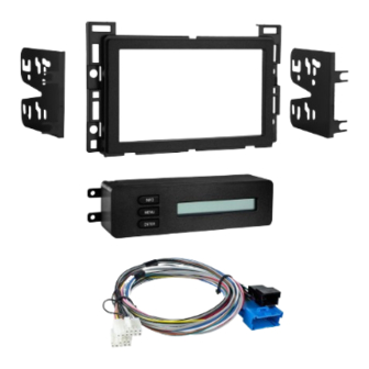
- Page 1 User Manual of Product 1: Metra 95-3303B Double DIN Dash Kit for Chevrolet and Pontiac (Black) User Manual of Product 2: Metra Axxess ASWC-1 Steering Wheel Control Interface...
- Page 2 INSTALLATION INSTRUCTIONS FOR PART 95-3303B APPLICATIONS Table of Contents Chevrolet: Malibu/Malibu Maxx 2004-2007, Dash Disassembly Malibu Classic 2008, Cobalt* 2005-2006 – Chevrolet Malibu 2004-2007......2-3 Pontiac G6** 2005-2009 – Chevrolet Malibu Classic 2008 ......2-3 95-3303B – Chevrolet Cobalt* 2005-2006 ....... 4 –...
- Page 3 95-3303B Dash Disassembly Chevrolet Malibu 2004-2007, 3. Remove (2) 7 mm screws from Chevrolet Malibu Classic 2008 bottom edge of panel below steering wheel. Unclip panel and 1. Unclip and remove wood grain/ let hang. It is not necessary to painted trim pieces from both completely remove panel.
- Page 4 95-3303B Dash Disassembly Chevrolet Malibu 2004-2007, 7. Unclip and remove trim panel Chevrolet Malibu Classic 2008 cont. surrounding radio and climate controls. (Figure G) 5. Unclip and remove side panel from 8. Remove (4) 7 mm screws from the passenger side of dash with door...
- Page 5 95-3303B Dash Disassembly Chevrolet Cobalt 2005-2006 4. Unclip and remove trim panel surrounding radio and climate 1. Unclip and remove trim panel from controls. (Figure D) above glove box. (Figure A) 5. Remove (4) 9/32” screws securing 2. Unclip upper edge of panel below radio.
- Page 6 95-3303B Dash Disassembly Pontiac G6 2005-2009 3. Unclip and remove center panel surrounding radio and A/C controls. 1. Open glove box and remove (6) (Figure C) screws from outer edge then 4. Remove (4) screws and extract unclip and remove box. (Figure A) radio from sub dash.
- Page 7 95-3303B Kit Assembly Wiring the 95-3303B ISO DDIN radio provision 1. Make wiring connections using the Metra/EIA Wiring Code chart, shown below, 1. Slide the appropriate bracket into and the instructions included with the radio. the trim plate aligning the holes in...
- Page 8 95-3303B Operation of the 95-3303B Setting and Adjustment mode Table 1.0 There is a Settings and Adjustments mode available for the individualized Function LCD Display Description of Operation adjustment of the contrast of the display, brightness of the display and backlighting, INFO increases LCD contrast OnStar volume, and the button backlighting color.
- Page 9 INSTALLATION INSTRUCTIONS FOR PART 95-3303B NOWLEDGE IS OWER Enhance your installation and fabrication skills by enrolling in the most recognized and respected mobile electronics school in our industry. Log onto www.installerinstitute.com or call 800-354-6782 for more information and take steps toward a better tomorrow.
- Page 10 INSTRUCCIONES DE INSTALACIÓN PARA LA PIEZA 95-3303B AplicAciones Indice Chevrolet: Malibu/Malibu Maxx 2004-2007, Desmontaje del tablero Malibu Classic 2008, Cobalt* 2005-2006 – Chevrolet Malibu 2004-2007......2-3 Pontiac G6** 2005-2009 – Chevrolet Malibu Classic 2008 ......2-3 95-3303B – Chevrolet Cobalt* 2005-2006 ....... 4 –...
- Page 11 95-3303B Desmontaje del tablero Chevrolet Malibu 2004-2007, 3. Retire los (2) tornillos de 7 mm del Chevrolet Malibu Classic 2008 borde inferior del panel debajo del volante. Desenganche el panel y 1. Desenganche y retire las piezas déjelo colgando. No es necesario de moldura de veta de madera/ retirar el panel por completo.
- Page 12 95-3303B Chevrolet Malibu 2004-2007, 7. Desenganche y retire el panel de Chevrolet Malibu Classic 2008 cont. moldura que rodea el radio y los controles del clima. (Figura G) 5. Desenganche y retire el panel lateral del lado del conductor del 8.
- Page 13 95-3303B Desmontaje del tablero Chevrolet Cobalt 2005-2006 4. Desenganche y retire el panel de moldura que rodea el radio y los 1. Desenganche y retire el panel de la controles del clima. (Figura D) moldura de arriba de la guantera.
- Page 14 95-3303B Desmontaje del tablero Pontiac G6 2005-2009 3. Suelte y retire el panel central que rodea el radio y los controles del 1. Abra la guantera y retire los (6) aire acondicionado. (Figura C) tornillos del borde exterior, luego 4. Quite los (4) tornillos y extraiga el desenganche y retire la guantera.
- Page 15 95-3303B Ensamble del kit Provisión de unidad central Cableado del 95-3303B ISO DDIN. 1. Haga las conexiones de cableado usando la tabla de código de cableado Metra/ EIA que se muestra a continuación y las instrucciones incluidas con el radio.
- Page 16 95-3303B Operación del 95-3303B Modo de configuración y ajustes Tabla 1.0 Hay un modo de configuración y ajustes disponible, asequible para el ajuste Función Pantalla LCD Descripción de la operación individualizado del contraste, brillo y retroiluminación de la pantalla, volumen de INFO aumenta el contraste LCD OnStar y el color de retroiluminación de los botones.
- Page 17 INSTRUCCIONES DE INSTALACIÓN PARA LA PIEZA 95-3303B EL CONOCIMIENTO ES PODER NOWLEDGE IS OWER Mejore sus habilidades de instalación y fabricación Enhance your installation and fabrication skills by inscribiéndose en la escuela de dispositivos electrónicos enrolling in the most recognized and respected mobile electronics school in our industry.
- Page 18 • ASWC-1 Interface • 12-pin harness with male 3.5mm connector • Female 3.5mm connector with Brown and Brown/White wires TOOLS REQUIRED • Cutting tool • Crimping tool • Tape METRA. THE WORLD’S BEST KITS. ® 1-800-221-0932 metraonline.com © COPYRIGHT 2017 METRA ELECTRONICS CORPORATION...
-
Page 19: Table Of Contents
Table of Contents Preface ....................3 Overview – Introduction to the ASWC-1 Interface and Wiring Harness ....4-5 ASWC-1 Installation – Connections to be Made ..............6-7 – Programming .................8-9 Auto Detect Mode: Overview ............8 Auto Detect Mode: Steps ............8-9 – Remapping the SWC (steering wheel control) Buttons ....10-11 Button Assignment Legend ............ -
Page 20: Preface
Preface What you need to know before you begin 1) Know the correct year, make, and model of your vehicle. 2) Ensure the steering wheel controls work before removing the factory radio, and know what the Volume Up button is. The Volume Up button is used for programming, so knowing this before removing the radio is crucial. -
Page 21: Overview
Overview Introduction to the ASWC-1 Interface and Wiring Harness On the top of the ASWC-1 interface there are three points of interest: 1) Programming LED 2) Reset Button 3) Update Port Cover (slide to open) Micro “B” Update Port Cover Reset Button* Programming LED *Note: The Reset button is recessed. - Page 22 Overview Below are the wire colors for the ASWC-1. Please visit the Axxess website at www.axxessinterfaces.com for detailed information on your specific vehicle and for what color wire(s) to use with the ASWC-1 interface. Pin-1 Pink Pin-7 Blue/Pink Pin-2 White/Green Pin-8 Black/Green Pin-3 Yellow/Green Pin-9 Red (tip of 3.5mm connector)
-
Page 23: Aswc-1 Installation Connections To Be Made
ASWC-1 Installation Connections to be made Once you have collected or printed out the “ASWC-1 Vehicle Instructions” for your particular vehicle, from www.axxessinterfaces.com, you’re ready to install the ASWC-1. Note: If wiring is not available on our website for your vehicle, you will need to obtain this yourself. - Page 24 ASWC-1 Installation Connections to be made B. For Metra OE radios: Connect the steering wheel control Key 1 wire (Gray) to the Brown wire of the ASWC-1. Isolate and tape the Brown/White wire, it will not be used. C. For Kenwood, or select JVC’s with a Blue/Yellow steering wheel control wire: Connect the Kenwood/JVC steering wheel control wire to the Brown wire of the ASWC-1.
-
Page 25: Programming
ASWC-1 Installation Programming The ASWC-1 can be programmed two different ways. It can auto program itself through Auto Detect Mode, or it can be manually programmed (pp. 19-21). The following, which is recommended, is for auto programming. Auto Detect Mode: Overview The ASWC-1 has the ability to auto detect select vehicles and what aftermarket radio it is connected to. - Page 26 ASWC-1 Installation Programming 4) After a few seconds the LED should stop flashing rapidly and go out for approximately 2 seconds. At this point do not press any buttons. 5) After the approximate 2 seconds there will be a series of 7 Green flashes, some short, and some long.
-
Page 27: Remapping The Swc (Steering Wheel Control) Buttons
ASWC-1 Installation Remapping the SWC buttons Let’s say you have ASWC-1 programmed to your radio and you want to change the button assignment for the steering wheel controls. For instance, you would like Seek Up to be Mute. Follow the steps below to remap the steering wheel control buttons: 1) Make sure the ASWC-1 is visible, so you can see the LED flashes to confirm button recognition. -
Page 28: Button Assignment Legend
ASWC-1 Installation Remapping the SWC buttons Button Assignment Legend 1. Volume Up 8. Preset Down 2. Volume Down 9. Power 3. Seek Up/Next 10. Band 4. Seek Down/Prev 11. Play/Enter 5. Source/Mode 12. PTT (Push to Talk)* 6. Mute 13. On Hook 7. -
Page 29: Changing Radio Type
ASWC-1 Installation Changing Radio Type 1) After 3 seconds of turning the key on, press and hold the Volume Down button on the steering wheel until the LED on the ASWC-1 goes solid. 2) Release the Volume Down button; the LED will go off indicating we are now in Changing Radio Type mode. -
Page 30: Radio Legend
ASWC-1 Installation Changing Radio Type Radio Legend 1. Eclipse (Type 1) 9. Valor 2. Kenwood 10. Clarion (Type 2) 3. Clarion (Type 1) 11. Metra OE 4. Sony and Dual 12. Eclipse (Type 2) 5. JVC 13. LG 6. Pioneer and Jensen 14. -
Page 31: Dual Assignment Instructions
ASWC-1 Installation Dual Assignment Instructions Nota: Seek Up and Seek Down are already set to Preset Up and Preset Down for a long button press. 1) Turn on the ignition but do not start the vehicle. 2) Press and hold down the steering wheel button, that you want to assign a long press function, for about 10 seconds until the LED rapidly flashes green. -
Page 32: Dual Assignment Legend
ASWC-1 Installation Dual Assignment Instructions Dual Assignment Legend Button Number New Button Action Not allowed Not allowed Seek Up/Next Seek Down/Prev Mode/Source Mute Preset Up Preset Down Power Band Play/Enter On Hook Off Hook Fan Up Fan Down Temp Up Temp Down... -
Page 33: Aswc-1 Troubleshooting Auto Detect Mode
ASWC-1 Troubleshooting Auto Detect Mode If the auto detect feature was tried and at the end the LED did not go solid, but instead continually flashes; this means that the ASWC-1 did not detect the vehicle. Follow these steps to determine what may have happened: 1) Verify that you have a 12-volt DC on the Red accessory wire of the ASWC-1, using a multimeter. - Page 34 ASWC-1 Troubleshooting Auto Detect Mode Note: If a pre-wired harness is being used and you have tried all the troubleshooting steps listed above, if the ASWC-1 still does not go to a solid LED, remove the pre-wired ASWC-1 harness and use the harness that came with the ASWC-1.
- Page 35 ASWC-1 Troubleshooting Auto Detect Mode 3) For Kenwood radios, make sure that the ASWC-1 displays that a Kenwood radio is being used; reference to Radio Legend (p. 21). If the Radio Legend shows a JVC radio instead, then reference to the Changing Radio Type (p.
-
Page 36: Manual Programming Mode
ASWC-1 Troubleshooting Manual Programming Mode If your vehicle is not listed for auto detection by the ASWC-1 on the Axxess website, www.axxessinterfaces.com, you may be able to manually program a non-data communication vehicle using the following steps. Tip: If you do not know if you have a data communication vehicle or not, refer to the “ASWC-1 Vehicle Instruction”... - Page 37 ASWC-1 Troubleshooting Manual Programming Mode 4) Next, press and hold the Volume Down button until the LED goes solid. Release the Volume Down button and the LED will turn off; Volume Down has now been programmed. 5) At this point refer the Manual Programming Legend (p. 21) and continue to the Seek Up/Next button.
-
Page 38: Manual Programming Legend
ASWC-1 Troubleshooting Manual Programming Mode 12) Press and hold down the Volume Down button until the LED goes solid. 13) Programming for the vehicle and the radio is now complete. Next, test the steering wheel control functions to make sure it works correctly. -
Page 39: Resetting Original Aswc-1 Settings
ASWC-1 Troubleshooting Resetting Original ASWC-1 Settings 1) Turn the ignition on and wait 3 seconds. 2) Press the Reset button for 3 seconds and then release. 3) Refer to the Programming section (pp. 8-9) to program the ASWC-1. 4) Once the LED is solid the ASWC-1 is reset and should be operating with the default settings. -
Page 40: Led Feedback
ASWC-1 Troubleshooting LED Feedback B. Radio LED Feedback (indicated by Red LED on the ASWC-1) LED flash is for Eclipse (Type 1) LED flash is for Kenwood LED flash is for Clarion (Type 1) LED flash is for Sony and Dual LED flash is for JVC LED flash is for Pioneer and Jensen LED flash is for Alpine*... - Page 41 Log onto www.installerinstitute.com or call 800-354-6782 for more information and take steps toward a better tomorrow. Metra recommends MECP certified technicians US. PAT. NOS. 8014920 and 8214105 1-800-221-0932 AXXESSINTERFACES.COM © COPYRIGHT 2017 METRA ELECTRONICS CORPORATION...
- Page 42 Interfase ASWC-1 • Arnés de 12pins con conector macho de 3.5mm • Conector hembra de 3.5mm con cables marrón/blanco HERRAMIENTAS REQUERIDAS • Cortador • Pelacables • Cinta METRA. THE WORLD’S BEST KITS. ® 1-800-221-0932 metraonline.com © COPYRIGHT 2017 METRA ELECTRONICS CORPORATION...
- Page 43 Índice Prefacio ..................... 3 Información general – Introduction to the ASWC-1 Interface and Wiring Harness ....4-5 Instalación del ASWC-1 – Conexiones que se deben hacer ............6-7 – Programación ................8-9 Modo de detección automática: Información general ....8 Modo de detección automática: Steps ........8-9 –...
-
Page 44: Prefacio
Prefacio Lo que debe saber antes de empezar 1) Conozca el año, marca y modelo correctos de su vehículo. 2) Asegúrese de que los controles en el volante funcionen antes de retirar el radio de fábrica y sepa cuál es el botón de aumentar volumen. El botón de aumentar volumen se usa para la programación, así... -
Page 45: Información General
Información general Introducción a la interfase ASWC-1 y al arnés de cables En la parte superior de la interfase ASWC-1 hay tres puntos de interés: 1) LED de programación 2) Botón de restablecimiento 3) Cubierta del puerto de actualización (deslice para abrirla) Micro “B”... - Page 46 Información general A continuación se indican los colores de los cables del ASWC-1. Visite el sitio web de Axxess en www.axxessinterfaces.com para obtener información detallada sobre su vehículo específico y para saber cuáles colores de cables usar con la interfase ASWC-1. Pin 1 Rosa Pin 7 Azul/Rosa Pin 2 Blanco/Verde...
-
Page 47: Instalación Del Aswc-1
Instalación del ASWC-1 Conexiones que se deben hacer Una vez que haya recolectado o impreso las “Instrucciones del vehículo con ASWC-1” sobre su vehículo específico en el sitio www.axxessinterface.com, está listo para instalar el ASWC-1. Nota: Si el cableado para su vehículo no está disponible en nuestro sitio web, necesitará... - Page 48 Instalación del ASWC-1 Conexiones que se deben hacer B. Para radios Metra OE: Conecte el cable Clave 1 (gris) del control en el volante con el cable marrón del ASWC-1. Aísle y encinte el cable marrón/blanco, no se utilizará. C. Para Kenwood o algunos JVC con cable del control en el volante azul/amarillo: Conecte el cable del control en el volante Kenwood/JVC con el cable marrón del ASWC-1.
-
Page 49: Programación
Instalación del ASWC-1 Programación El ASWC-1 puede programarse de dos maneras diferentes. Puede programarse automáticamente por sí solo mediante el modo de detección automática o puede programarse manualmente (págs. 19 a 21). Se recomienda lo siguiente para la programación automática. Modo de detección automática: Información general El ASWC-1 tiene la capacidad de detectar automáticamente algunos vehículos y a cuál radio de mercado secundario está... - Page 50 Instalación del ASWC-1 Programación y no iluminarse durante aproximadamente 2 segundos. En este momento, no presione ningún botón. 5) Después de aproximadamente 2 segundos, habrá una serie de 7 parpadeos de color verde, algunos cortos y algunos largos. Los parpadeos largos representan los cables que son reconocidos por el ASWC-1.
-
Page 51: Remapeo De Los Botones Swc
Instalación del ASWC-1 Remapeo de los botones SWC Digamos que tiene el ASWC-1 programado para su radio y ahora quiere cambiar la asignación de los botones para los controles del volante. Por ejemplo, le gustaría que el botón de buscar siguiente funcionara como silencio. -
Page 52: Leyenda De Asignación De Botones
Instalación del ASWC-1 Remapeo de los botones SWC Leyenda de asignación de botones 1. Subir volumen 8. Bajar prestablecido 2. Bajar volumen 9. Encendido 3. Buscar siguiente 10. Banda 4. Buscar anterior 11. Reproducir/Aceptar 5. Fuente/Modo 12. PTT (presionar para hablar) 6. -
Page 53: Cambio De Tipo De Radio
Instalación del ASWC-1 Cambio de tipo de radio 1) Después de 3 segundos de girar la llave a encendido, presione y mantenga presionado el botón de bajar volumen en el volante hasta que el foco LED en el ASWC-1 se encienda sin parpadear. 2) Suelte el botón de bajar volumen, el foco LED se apagará... -
Page 54: Leyenda De Radio
Instalación del ASWC-1 Cambio de tipo de radio Leyenda de radio 1. Eclipse (Tipo 1) 9. Valor 2. Kenwood 10. Clarion (Tipo 2) 3. Clarion (Tipo 1) 11. Metra OE 4. Sony and Dual 12. Eclipse (Tipo 2) 5. JVC 13. -
Page 55: Instrucciones De Asignación Dual
Instalación del ASWC-1 Instrucciones de asignación dual Nota: Los botones buscar siguiente y buscar anterior ya están configurados en subir prestablecido y bajar prestablecido al presionar y sostener el botón. 1) Encienda la ignición pero no encienda la marcha del vehículo. 2) Presione y sostenga el botón del volante al que desea asignar a una función de presionar y sostener, durante al menos 10 segundos hasta que el foco LED parpadee rápidamente de color verde. -
Page 56: Leyenda De Asignación Dual
Instalación del ASWC-1 Instrucciones de asignación dual Leyenda de asignación dual Número de botón Nueva acción del botónn No se permite No se permite Buscar siguiente Buscar anterior Modo/Fuente Silencio Subir prestablecido Bajar prestablecido Potencia Banda Reproducir/Aceptar Colgado Descolgado Aumentar ventilador Disminuir ventilador Aumentar temperatura Disminuir temperatura... -
Page 57: Resolución De Problemas De Aswc-1 Modo De Detección Automática
Resolución de problemas de ASWC-1 Modo de detección automática Si la función de detección automática se intentó y al final el foco LED no se encendió sin parpadear, sino que parpadeó continuamente; esto significa que el ASWC-1 no detectó el vehículo. Siga estos pasos para determinar qué... - Page 58 Resolución de problemas de ASWC-1 Modo de detección automática Nota: Si se usa un arnés precableado y ha intentado todos los pasos de resolución de problemas mencionados anteriormente, si foco LED del ASWC-1 aún no se enciende sin parpadear, retire el arnés precableado del ASWC-1 y use el arnés que venía con el ASWC-1.
- Page 59 Resolución de problemas de ASWC-1 Modo de detección automática 3) Para los radios Kenwood, asegúrese de que el ASWC-1 muestre que se está usando un radio Kenwood, consulte leyenda del radio (pág. 21). Si al contrario la leyenda del radio muestra radio JVC, entonces consulte el cambio de tipo de radio (pág.
-
Page 60: Modo De Programación Manual
Resolución de problemas de ASWC-1 Modo de programación manual Si su vehículo no se encuentra en la lista de la detección automática del ASWC-1 en el sitio web de Axxess, www.axxessinterfaces.com, es posible que pueda programar manualmente un vehículo sin comunicación de dados usando los siguientes pasos. - Page 61 Resolución de problemas de ASWC-1 Modo de programación manual 4) Ahora presione y mantenga presionado el botón de bajar volumen hasta que el foco LED se encienda sin parpadear. Suelte el botón de bajar volumen y el foco LED se apagará, ya quedó programado el botón de bajar volumen.
-
Page 62: Manual Programación Legend
Resolución de problemas de ASWC-1 Modo de programación manual Nota: Si el número de parpadeos no coincide con el radio que ha instalado, consulte la sección de cambio de tipo de radio (pág. 13). 12) Presione y mantenga presionado el botón de bajar volumen hasta que el foco LED se ilumine sin parpadear. -
Page 63: Restablecimiento De Los Ajustes Originales De Aswc-1
Resolución de problemas de ASWC-1 Restablecimiento de los ajustes originales de ASWC-1 1) Encienda la ignición y espere 3 segundos. 2) Presione el botón de restablecimiento durante 3 segundos y luego suéltelo. 3) Consulte la sección de programación (páginas 8 y 9) para programar el ASWC-1. -
Page 64: Retroalimentación Led
Resolución de problemas de ASWC-1 Retroalimentación LED B. Retroalimentación LED del radio (indicada por el foco LED de color rojo en el ASWC-1) El 1er parpadeo del foco LED es para Eclipse (Tipo 1) El 2o parpadeo del foco LED es para Kenwood El 3er parpadeo del foco LED es para Clarion (Tipo 1) El 4o... - Page 65 Metra recomienda técnicos con certificación del Programa de Certificación en Electrónica Móvil (Mobile Electronics Certification Program, MECP). US. PAT. NOS. 8014920 y 8214105 1-800-221-0932 AXXESSINTERFACES.COM © COPYRIGHT 2017 METRA ELECTRONICS CORPORATION...
Need help?
Do you have a question about the 95-3303B and is the answer not in the manual?
Questions and answers