Baroness LM101 Owner's Operating Manual
Floating head greens mower
Hide thumbs
Also See for LM101:
- Owner's operating manual (81 pages) ,
- Owner's operating manual (91 pages)

Subscribe to Our Youtube Channel
Related Manuals for Baroness LM101


Summary of Contents for Baroness LM101
- Page 1 Floating Head Greens Mower Owner's Operating Manual Serial No. LM101:10343- "Required reading" Read this manual and the Owner's Manual for the engine before using the machine. Original Instructions Ver.2.0...
- Page 2 LM101 Regulations California Proposition65 (For California, USA) WARNING: This product can expose you to chemicals including Carbon Monoxide, which is known to the State of California to cause birth defects or other reproductive harm. For more information go to www.P65Warnings.ca.gov.
- Page 3 LM101 Greeting Thank you for purchasing the Baroness product. This manual describes the proper handling, adjustment, and inspection of your product. We hope you will use the product safely, and take advantage of its best performance.
- Page 4 The operator is responsible for operating the product properly and safely. Maintenance should only be performed by a certified specialist. If you have any questions concerning maintenance or genuine parts, please contact a Baroness dealer or Kyoeisha. When making inquiries about the product, please specify the product's model designation and serial number.
- Page 5 When replacing parts, be sure to use genuine Baroness parts or parts designated by Kyoeisha. Note that the Baroness product warranty may not apply to defects caused by the use of parts from other companies. Prior to use, carefully read the following manuals to thoroughly understand the contents for safe and correct operation.
- Page 6 LM101 Introduction...
-
Page 7: Table Of Contents
LM101 Contents Safety .............. Page 1-1 Safe Operating Practices .......Page 1-2 Disposal ............Page 2-1 Recycle and Waste Disposal ......Page 2-2 Product Overview .......... Page 3-1 Specifications ..........Page 3-2 Carbon Dioxide (CO2) Emissions Measurement ..........Page 3-3 Names of Each Section ......... Page 3-4 Regulation Decals ..........Page 3-5... - Page 8 LM101 Contents...
-
Page 9: Safety
LM101 Safety Safe Operating Practices ...... Page 1-2 Training ..........Page 1-2 Preparation ..........Page 1-2 Operation ..........Page 1-3 Maintenance and Storage ..... Page 1-4 Page 1-1... -
Page 10: Safe Operating Practices
LM101 Safety Failure to adequately follow these safety Preparation precautions may cause an accident resulting in injury or death. Evaluate the terrain to determine what accessories and attachments are needed to Danger Danger properly and safety perform the job. This product is designed to ensure safe... - Page 11 LM101 Safety Stop the engine in the following conditions. Operation Before refueling. Do not operate the engine in a confined Before removing the grass catcher/ space where dangerous carbon monoxide catchers. fumes can collect. Before making height adjustment unless Only operate in good light, keeping away adjustment can be made from the from holes and hidden hazards.
- Page 12 LM101 Safety When transporting the machine on a truck or Use jack stands to support components a trailer, set the parking brake, stop the when required. engine, and fasten the machine to the truck Carefully release pressure from components with a rope or other suitable restraining with stored energy.
-
Page 13: Disposal
LM101 Disposal Recycle and Waste Disposal ....Page 2-2 About Recycle ........Page 2-2 About Waste Disposal ......Page 2-2 Page 2-1... -
Page 14: Recycle And Waste Disposal
LM101 Disposal Recycle and Waste Disposal About Recycle Recycling battery etc. is recommended for environmental conservation and economical use of resources. It may be required by local laws. About Waste Disposal Make sure that waste generated when servicing or repairing the machine is disposed of in accordance with local regulations. -
Page 15: Product Overview
LM101 Product Overview Specifications ........Page 3-2 Specifications .........Page 3-2 Sound Pressure Level ......Page 3-3 Sound Power Level ....... Page 3-3 Vibration Level ........Page 3-3 Carbon Dioxide (CO2) Emissions Measurement ..........Page 3-3 Names of Each Section ......Page 3-4 Regulation Decals ........Page 3-5... -
Page 16: Specifications
LM101 Product Overview Specifications Specifications Model LM101 Total with grass catcher 61.02 in 155 cm length Total Dimensions without traveling wheel 37.01 in 94 cm width Total Steering handle 45.67 in 116 cm height Total weight (empty fuel tank) 251.32 lb... -
Page 17: Carbon Dioxide (Co2) Emissions Measurement
LM101 Product Overview Sound Pressure Level Sound Pressure Level This machine was confirmed to have a continuous A-weighted sound pressure level of 84 dB by measuring identical machines in accordance with the procedure specified in ISO5395-1:2013. Sound Power Level Sound Power Level... -
Page 18: Names Of Each Section
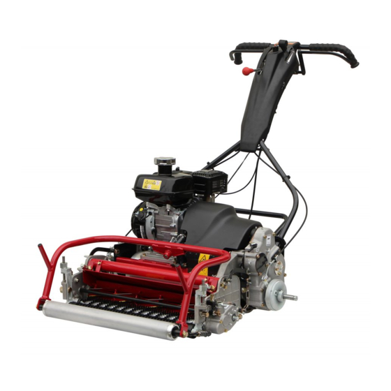
LM101 Product Overview Names of Each Section Handle Throttle lever Engine switch Main clutch lever Clutch lock lever Brake lever Engine Engine clutch cover Light Reel cutter Bed knife Front roller Rear roller Grass catcher roller Grass catcher Groomer Groomer clutch lever... -
Page 19: Regulation Decals
LM101 Product Overview Regulation Decals Specification Decal (For Europe) Positions of Regulation Decals The Specification decal indicates the CE marking, model , and weight, etc. C B E,F quwxcl-205 Positions of Regulation Decals_001 kj8jic-001 Specification Decal_001 Serial number plate Specification Decal... -
Page 20: Safety Signs And Instruction Signs
If they are damaged, become dirty, or peel off, replace them with new ones. Part numbers for decals that need to be replaced are listed in the parts catalog. Order them from a Baroness dealer or Kyoeisha. bfaymx-001 Positions of Safety Decals and Instruction... -
Page 21: Description Of Safety Decals And Instruction Decals
LM101 Product Overview Description of Safety Decals and PTO caution decal Instruction Decals K4205001760 Handling caution decal DECAL, CAUTION PTO Warning K4205002150 DECAL, CAUTION HANDLING May catch your arm - Keep away from PTO moving parts during the engine running. - Page 22 LM101 Product Overview Caution to Noise Decal Greasing Each 10-Hours Decal K4205001330 K4209000370 DECAL, CAUTION TO NOISE DECAL, GREASING EACH 10-HOURS Add grease every 10 hours. bwu9po-001 rc9mq6-001 Caution to Noise Decal_001 Greasing Each 10-Hours Decal_001 Engine Oil Warning Decal...
-
Page 23: Handling Instructions
LM101 Handling Instructions Preparation for Use ....... Page 4-2 Throttle Lever ........Page 4-22 Throttle Lever ........Page 4-23 Installing the Handle ......Page 4-2 Brake Lever ......... Page 4-23 Connection of Engine Switch Cord ..Page 4-2 Clutch Lock Lever ........ Page 4-23 Installing The Stand ....... -
Page 24: Preparation For Use
LM101 Handling Instructions The crimp terminal is secured to the engine Preparation for Use crankcase with a hexagon bolt. Installing the Handle Put the handle pin on the left frame into the hole at the left-side lower edge of the handle. -
Page 25: Inspections
LM101 Handling Instructions Tighten the bolt, washer, and nut at the left Make sure that the reel cutter (cutting side of the stand that were temporarily cylinder) and the bed knife (bottom blade) secured. are not cracked. Check to see how much the reel cutter (cutting cylinder) and the bed knife (bottom blade) are worn. -
Page 26: Air Cleaner
LM101 Handling Instructions Remove dirt and dust from the paper Air Cleaner element with blowing air or patting. Inspection of Air Cleaner Assemble the paper and urethane elements. The air cleaner is a component that removes Attach the air cleaner elements with the dirt from the intake air to prevent wear of the screw. -
Page 27: Roller
LM101 Handling Instructions Roller Wire Inspection of Rollers Inspection of Wire Bearing wear due to frequent use or bearing Make sure that the wire is not cracked or damage caused by water infiltration may damaged. prevent the roller from rotating smoothly. -
Page 28: Fuel
LM101 Handling Instructions The appropriate engine oil level should be Screw the oil level gauge firmly. between the upper and lower limit lines on the gauge. bgmiun-019 Supply of Engine Oil_001 bgmiun-015 Oil level gauge (Oil filling port) Inspection of Engine Oil_002... -
Page 29: Oil Leakage
LM101 Handling Instructions Oil Leakage Fuel Supply Inspection of Oil Leakage Caution After approximately 50 hours of operation, Do not supply fuel above FULL level of the some joints may be loosened and oil and fuel gauge. grease may leak. -
Page 30: Tightening Torques
LM101 Handling Instructions Tightening Torques Important Refer to the Tightening Torque table. Note that the Baroness product warranty may not apply to defects caused by incorrect or overtorque tightening, etc. Standard Tightening Torques Bolts and Nuts Important A number of bolts are used in each part of this machine. - Page 31 LM101 Handling Instructions General bolt Strength classification 4.8 Nominal diameter tib3yb-001 kgf-cm lb-in 3 - 5 30.59 - 50.99 26.55 - 44.26 7 - 9 71.38 - 91.77 61.96 - 79.66 14 - 19 142.76 - 193.74 123.91 - 168.17 29 - 38 295.71 - 387.49...
-
Page 32: Principal Tightening Torques
LM101 Handling Instructions Principal Tightening Torques Tightening Torque by Model LM101 Tighten the following bolts and nuts at the torque specified in the table. For thread locking adhesive, apply a middle strength thread locker (ThreeBond 1322 or equivalent anaerobic sealant). -
Page 33: Adjustment Before Work
LM101 Handling Instructions Adjustment before Work FOC (High/Low Clip) selector lever High clip Adjustment of Handle Low clip The height of the handle can be adjusted Stop according to the operator's working position. Adjust the engagement between the reel Move the handle adjusters supporting the cutter (cutting cylinder) and the bed knife handle up or down and fix them with the bolts. -
Page 34: Adjustment Of Cutting Height
LM101 Handling Instructions Cutter adjustment nut Loosen Tighten Adjustment of Cutting Height Adjust the cutting height to fit your cutting work. Important This applies the set cutting height that differs from the actual cutting height. Cutting Height and Thickness of Bed Knife... - Page 35 LM101 Handling Instructions Decide on the orientation of bolt B to suit Adjustment of Rear Roller the desired cutting stance, and install the rear roller assy. The rear roller can be adjusted to 3 levels. Cutting stance Adjust the rear roller to a cutting stance that suits the required work.
- Page 36 LM101 Handling Instructions Less aggressive cutting stance Loosen the left and right nuts that secure ・ Short offset distance and small bed knife the roller bracket. angle. 3kws2a-016 3kws2a-022 Adjustment of Front Roller_002 Adjustment of Rear Roller_005 Front roller Reel cutter...
-
Page 37: Adjustment Of Groomer
LM101 Handling Instructions Raise or lower the front roller with the roller Important adjustment bracket to set the position of the front roller so that there is no clearance with Setting the front groomer too deep applies too the bottom of the head of the cutting height... - Page 38 LM101 Handling Instructions Front groomer Front roller High nut Roller bracket Nut A Front groomer Nut B Reel cutter Groomer adjustment screw Bed knife Rear roller Loosen the bolt securing the right side Cutting height gauge groomer adjustment screw. Cutting height setting screw Loosen the right side high nut.
-
Page 39: Procedure To Start/Stop Engine
LM101 Handling Instructions Procedure to Start/Stop Engine Start/Stop of Engine Procedure to Start Engine Caution Before starting the engine, make sure that there are no other people or obstacles around the machine. 2qrq2r-010 Adjustment of Groomer_006 Caution Front groomer Make sure that the engine clutch cover is High nut installed in the prescribed position. - Page 40 LM101 Handling Instructions Don't grip the main clutch lever. Set the choke lever to the "Close" position. k7k67l-004 v2e27i-056 Procedure to Start Engine_003 Procedure to Start Engine_006 Main clutch lever Choke lever Clutch lock lever Close Open Important Set the fuel cock to the "Open" position.
- Page 41 LM101 Handling Instructions Set the choke lever to the "Open" position. Engine switch Make sure that the brake is locked. Set the fuel cock to the "Close" position. v2e27i-057 Procedure to Start Engine_008 Choke lever Close Open dgvd7o-006 Procedure to Stop Engine Procedure to Stop Engine_003 Don't grip the main clutch lever.
-
Page 42: Operation Method
LM101 Handling Instructions Description of Operation Decals Operation Method Engine Switch Mark Cautions before Leaving The Machine Caution ENGINE SWITCH MARK It illustrates the positions of the engine switch. Park the machine on a flat place. Do not park the machine on a slope. - Page 43 LM101 Handling Instructions ONOFF mark A (unit clutch) Reel rotation indication mark K4203001140 K4203001690 STICKER, ON/OFF A (unit clutch) STICKER, REEL ROTATION It shows ON/OFF of the unit clutch. It illustrates High / Low speed of the reel cutter rotation speed.
-
Page 44: Light Switch
LM101 Handling Instructions Engine Switch Red Alignment Mark 10300 Note: The engine switch is located in the handle. Depending on the specifications, this function To start the engine, set the engine switch to may not be available. the “ON” position, and to stop it, set to the K4209001230 “OFF”... -
Page 45: Brake Lever
LM101 Handling Instructions Throttle Lever Note: Depending on the specifications, this function may not be available. The throttle lever is located in the handle and enables you to adjust the engine rpm. Move the throttle lever toward the "High speed"... -
Page 46: Main Clutch Lever
LM101 Handling Instructions Main Clutch Lever Caution Avoid quick operation. Carefully and slowly operate the machine. Important The main clutch is not activated unless the safety lock released. dckng4-001 Drum Clutch Lever_001 The main clutch lever is located in the handle. -
Page 47: Foc (High/Low Clip) Selector Lever
LM101 Handling Instructions Note: Engine Clutch Cover Set the lever to the OFF position when traveling. The engine clutch cover is on the left side of the engine, covering the engine clutch. FOC (High/Low Clip) Selector Lever The engine clutch cover can be opened and... -
Page 48: Instruments
LM101 Handling Instructions Groomer Clutch Lever Instruments Note: Hour Meter Depending on the specifications, this function The hour meter indicates the accumulated may not be available. operation time of the engine. Caution The accumulated time can not be manually reset. -
Page 49: Cutting Work
LM101 Handling Instructions Removing/Installing Traveling Tires Cutting Work Cutting Work Important Remove the traveling tires before cutting Warning work. Do not operate on a steep slope. Traveling tires are used to travel. Removing Traveling Tires: Caution Stop the engine. Do not start to move or stop the machine Flip down the stand. -
Page 50: Removing/Installing Grass Catcher
LM101 Handling Instructions Important Make sure that the wheel mount plate is grooved on the drum shaft. Otherwise the tires may come off. x9pzjh-007 Removing/Installing Traveling Tires_003 Traveling tire Repeat the same process for removing the opposite traveling tire. x9pzjh-005... -
Page 51: Transporting
LM101 Handling Instructions Transporting Transporting Procedure Caution When loading and unloading the machine, wear non-slip shoes and travel slowly. Important When securing the machine with a rope, do not tie the rope to the engine. Important When securing the machine with a rope, be careful not to bend any wires. - Page 52 LM101 Handling Instructions Page 4-30 Storage...
-
Page 53: Maintenance
LM101 Maintenance Maintenance Precautions ..... Page 5-2 Position of Mower during Maintenance ........... Page 5-2 Maintenance Schedule ......Page 5-4 Adjusted Values ........Page 5-6 Greasing ..........Page 5-7 About Greasing ........Page 5-7 Greasing Points ........Page 5-7 Lubrication ........... Page 5-11 About Lubrication .........Page 5-11... -
Page 54: Maintenance Precautions
Set the handle so that the maintenance stand can stand upright. Important For the safe and best performance of your machine, use Baroness genuine parts for replacement and accessories. Please note that our product warranty may be void if you use non-genuine parts for replacement or accessories. - Page 55 LM101 Maintenance For maintenance of the machine without the ・ traveling wheels: Caution The engine malfunction does not occur even when the machine tilting toward the handle side with the stand touching the ground. Pay attention to the machine standing up depending on the unbalanced state owing to the adjusted position of the handle height.
-
Page 56: Maintenance Schedule
LM101 Maintenance Maintenance Schedule LM101 Follow the maintenance schedule below. ○・・・Inspect, adjust, supply, clean ●・・・Replace (first time) △・・・Replace Maintenance Item Remarks Check tightening bolts and nuts ○ Check fuel level ○... - Page 57 LM101 Maintenance Maintenance Item Remarks Check main clutch lever ○ actuation Check brake function ○ ...
-
Page 58: Adjusted Values
Regrind blades (Reel cutter) ○ as and when required *1: Consult your local Baroness Dealer for this service. ・ *2: Refer to the Engine's Owner's Manual. ・ The values for consumables are not guaranteed. -
Page 59: Greasing
LM101 Maintenance Greasing No. of Greasing Location greasing period About Greasing points Upper side of left frame cover Since there may be adhesion or damage due Mower #1 shaft to lack of grease on moving parts, they must be greased. - Page 60 LM101 Maintenance Left frame #2 shaft Right gear case 8bq62b-300 8bq62b-304 Greasing Points_004 Greasing Points_008 Left frame #4 shaft Transmission gear case 8bq62b-301 8bq62b-305 Greasing Points_005 Greasing Points_009 Differential gear Transmission shaft There are one location each on the right and left.
- Page 61 LM101 Maintenance Right side Right side 8bq62b-307 8bq62b-310 Greasing Points_011 Greasing Points_014 Arm mounting hitch fulcrum Front roller There are one location each on the right and left. Left side 8bq62b-308 Greasing Points_012 Reel housing There are one location each on the right and 8bq62b-311 left.
-
Page 62: Greasing Points
LM101 Maintenance Groomer gear case Handle Note: Main clutch lever ・ Depending on the specifications, this function may not be available. 8bq62b-447 Greasing Points_020 8bq62b-313 Greasing Points_017 Groomer shaft Note: Depending on the specifications, this function may not be available. -
Page 63: Lubrication
LM101 Maintenance Clutch lock lever fulcrum Lubrication About Lubrication It is necessary to lubricate moving parts so that they will not become stuck or damaged. The locations where lubricant is used are indicated in "Lubricating Points". Apply the lubricant. Lubricating Points... -
Page 64: Maintenance Work
LM101 Maintenance Adjusting CAM Maintenance Work Turn the cam bush on both sides of the bed Adjustment of Cutter Adjustment Spring knife (bottom blade), and the blade can be raised and lowered respectively by maximum Caution 0.3 mm (0.012 in). -
Page 65: Back Lapping
Have the following items ready: Strips of Lowering the bed knife. newspaper, Abrasive [Back lapping powder Back Lapping mixed with oil; or gel compound (Baroness genuine abrasive)], Brush. Back lapping is work similar to sharpening a cooking knife. If the edges of the reel cutter... - Page 66 LM101 Maintenance Have a lapping machine or the lapping Insert one or two strips of newspaper into the handle ready. space between the reel cutter (cutting cylinder) and the bed knife (bottom blade) at Caution an angle of 90 degrees. Then, rotate the reel...
- Page 67 LM101 Maintenance Connect the lapping machine or the lapping Wash off or wipe off with a cloth, etc., the handle to the lapping bolt on the machine. abrasive from the reel cutter (cutting cylinder), and then check it for sharpness.
-
Page 68: Sharpening Of Reel Cutter (Cutting Cylinder)
For sharpening the reel cutter (cutting Sharpening is necessary when the reel cutter cylinder), contact your dealer or Baroness. (cutting cylinder) reaches a condition described If the outer diameter of the reel cutter (cutting below. cylinder) after sharpening is more than the... -
Page 69: Replacement Of Reel Cutter (Cutting Cylinder)
LM101 Maintenance Usage limit of Usage limit Outer diameter of reel sharpening width for Dimension B Dimension B cutter (cutting cylinder) outer diameter of reel (Distance (Distance (new part) Dimension A Dimension A cutter (cutting cylinder) from blade from blade... - Page 70 11.5 mm (0.453 in) Important Mower with Groomer: See the list in Tightening torques. Note that the Baroness product warranty may not apply to defects caused by incorrect or overtorque tightening etc. Follow the instruction below to replace the reel cutter bearing and oil seal on both sides.
-
Page 71: Replacement Of Bed Knife (Bottom Blade)
LM101 Maintenance Replacement of Bed Knife (Bottom Blade) Removing/Installing The Bed Knife Base Removal of Bed Knife Base Caution Both the reel cutter (cutting cylinder) and the Caution bed knife (bottom blade) are edged tools. Both the reel cutter (cutting cylinder) and the Handle them carefully, since they could cut bed knife (bottom blade) are edged tools. - Page 72 LM101 Maintenance Turn over the cutting section. Stand up the cutting section so that the roller bracket is at the top, and then remove the left and right cutter adjustment nuts. 5ttm1g-007 Removal of Bed Knife Base_003 5ttm1g-010 Cutting section...
- Page 73 LM101 Maintenance Installation of Bed Knife Base Collar Compression spring Caution Cutter adjustment bolt Bed knife base COMP Both the reel cutter (cutting cylinder) and the Mower frame bed knife (bottom blade) are edged tools. Handle them carefully, since they could cut Temporarily install the left and right cutter your hands and feet.
- Page 74 LM101 Maintenance Make sure that the bed knife (bottom blade) Adjust the positions of the cam bushes so contacts the reel cutter (cutting cylinder). that both sides cut. kx7caa-005 kx7caa-012 Installation of Bed Knife Base_004 Installation of Bed Knife Base_006...
- Page 75 LM101 Maintenance Bed knife base COMP Lock nut Collar Cutter pin Compression spring Cam bush Cutter adjustment bolt Install the rear roller Assy. Install the bed knife base COMP. Tighten the left and right cutter adjustment nuts evenly on both sides so that the cutter pin mounting holes of the bed knife base and cam bush are aligned.
-
Page 76: Removing/Installing The Bed Knife
LM101 Maintenance Removing/Installing The Bed Knife Important Be sure not to scratch the bed knife base Removing The Bed Knife surface where the bed knife shall be mounted. Remove rust and dust. Caution Both the reel cutter (cutting cylinder) and the Important bed knife (bottom blade) are edged tools. -
Page 77: Adjustment Of Brake
LM101 Maintenance Adjustment of Brake Brake lever Lock Caution Unlock If the brake wire is severed, this machine will Loosen all the brake wire lock nuts on the be unable to stop. underside of the handle cover. If there are cracks, damage, or other defects, Raise or lower the adjustment bolt with the replace it immediately. -
Page 78: Adjustment Of Engine Clutch Section
LM101 Maintenance Tighten all the lock nuts after making the Replacement of Engine Oil necessary adjustments. Note: Caution If there is a rubbing noise when rotating the drum or the drum feels difficult to turn, the Be careful with hot oil, which could cause brake shoes may be making contact with the burns if it contacts your skin. - Page 79 LM101 Maintenance Position the machine so that the engine will be level, then check the engine oil level without screwing the oil level gauge into the oil filling port. bgmiun-019 Replacement of Engine Oil_001 Oil level gauge (Oil filling port)
-
Page 80: Troubleshooting Procedures Of Aftercut Appearance
LM101 Maintenance Angled Mismatch Troubleshooting Procedures of Aftercut Appearance Is the cutting height on both sides adjusted to be the same? Scalping Adjustment of cutting height Is the roller bracket secured? Is the bed knife (bottom blade) chipped? Tightening to secure... -
Page 81: Overlap Marks
LM101 Maintenance Overlap Marks Has the bed knife (bottom blade) become curved? Back lapping Surface grinding of bed knife (bottom blade) Replacement of bed knife (bottom blade) Loosening of blade engagement After loosening blade engagement, streaks still appear. Adjustment of spring compression length Is the spring pressure for the adjustment nut too light? (See "Adjustment of Cutter Adjustment Spring".) -
Page 82: Blade Does Not Cut
LM101 Maintenance Blade Does Not Cut Are genuine parts used for the blades? Is the grit size of the lapping Use lapping powder with a grit Replacement of blades with genuine parts powder #200 – #400? size of #200 – #400. -
Page 83: Uneven Blade Engagement
LM101 Maintenance Uneven Blade Engagement The unevenness is a difference of tightening torque between the left and right cutter adjustment nuts, or blade engagement on only one side, which cannot be adjusted. Promptly resolve the issue in order to maintain the optimum performance of the machine. - Page 84 LM101 Maintenance Page 5-32 Troubleshooting Procedures of Aftercut Appearance...
- Page 88 1-26, Miyuki-cho, Toyokawa-city, Tel : +81 - 533 - 84 - 1390 Head Office Fax : +81 - 533 - 84 - 1220 Aichi-pref, 442-8530 JAPAN LM101---UM--GBZ/20A-00-S.K E01[LM101_EU01]...
Need help?
Do you have a question about the LM101 and is the answer not in the manual?
Questions and answers