Degelman M28 Reference Manual
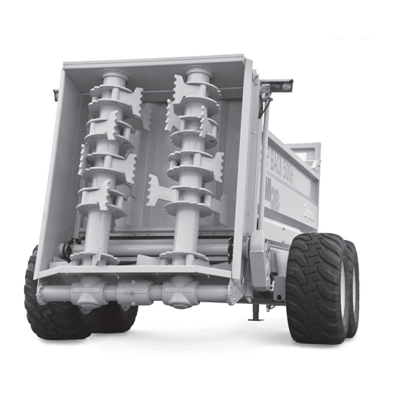
Manure spreader
Hide thumbs
Also See for M28:
- Operator's & parts manual (45 pages) ,
- Operator's & parts manual (56 pages)
Table of Contents
Advertisement
Quick Links
D E G E L M A N
I N D U S T R I E S
B O X
8 3 0 - 2 7 2
I N D U S T R I A L
R E G I N A ,
S K ,
C A N A D A ,
F A X 3 0 6 . 5 4 3 . 2 1 4 0
P H 3 0 6 . 5 4 3 . 4 4 4 7
1 . 8 0 0 . 6 6 7 . 3 5 4 5
D E G E L M A N . C O M
L P
D R I V E ,
S 4 P
3 B 1
RATE CONTOL SYSTEM
REFERENCE MANUAL
MANURE SPREADER M28/M34
OPTIONAL RATE CONTROL SYSTEM
142670 v1.1
Advertisement
Table of Contents

Related Manuals for Degelman M28


Summary of Contents for Degelman M28
- Page 1 RATE CONTOL SYSTEM REFERENCE MANUAL 142670 v1.1 MANURE SPREADER M28/M34 D E G E L M A N I N D U S T R I E S B O X 8 3 0 - 2 7 2 I N D U S T R I A L...
-
Page 3: Table Of Contents
TABLE OF CONTENTS Variable Rate Control Quick-Start Introduction / Installing GPS Terminator Box Cable Connection Power On / Main Screen INFO Screen / SETUP Screen Tare Load Cells / Load Spreader Select Product / Insert Desired Rate Begin Spreading End of Run / Use of Stop Button Manual Mode / Reverse Floor Setting Alarms Troubleshooting... -
Page 4: Variable Rate Control Quick-Start
Variable Rate Control Quick-Start INTRODUCTION The Degelman variable rate control package comes with the following components: A. NT8000i Head Unit Control Module B. Tractor Terminator Box Cable C. 6M extension Cable D. GPS KIT E. RAM Mount for Control Module Digi-Star Manuals &... -
Page 5: Power On / Main Screen
Variable Rate Control Quick-Start POWER ON / MAIN SCREEN POWER ON / MAIN SCREEN 1. Push the power button on the Control Module to turn it on. The screen will power on & display the main screen. Note: Refer to the DIGI-STAR operation manual provided to walk you through the display screens more in depth. -
Page 6: Tare Load Cells / Load Spreader
Variable Rate Control Quick-Start TARE LOAD CELLS 1. Once the spreader is hooked up & the unit is powered on the load cells must be set to 0. To do this first go to the INFO screen. 2. Next, click the “Load Cells Option” button. 3. -
Page 7: Begin Spreading
Variable Rate Control Quick-Start BEGIN SPREADING 1. Now the spreader is ready to spread. Pull the Note: If the floor conveyor does not begin moving spreader to its desired location & stop. the red stop button on the terminator junction cable may have been pushed. -
Page 8: Manual Mode / Reverse Floor
Variable Rate Control Quick-Start MANUAL MODE / REVERSE FLOOR Under normal operating conditions you will not need to select this mode, however, in the event you experience a problem with automatic control (if for example the beaters plug or a sensor has stopped working), you can control the floor chain manually. - Page 9 142670 - Rate Control System (29-April-2019)
-
Page 10: Troubleshooting
Troubleshooting TROUBLESHOOTING In the following section, we have listed some of the problems, causes and solutions that you may encounter. If you encounter a problem that is difficult to solve, even after having read through this troubleshooting section, please call your local dealer or distributor. - Page 11 Troubleshooting REFERENCE - “SET UP PRODUCTS” VALUES 1. From the “Options Menu” select the “Product” option on the bottom left. Ensure the settings are correct for each product option as shown below: 2. Select the “Light Product” option. Rate = 2.0 t/ac ‘T’...
-
Page 12: Component Routing Overview
Component Routing Overview LOAD CELLS - COMPONENT ROUTING OVERVIEW Rate Control Kit (Refer to Components Below) Main Load Cell Components 131763 - Junction Box, 6 Port - Ref #404721 131761 - Weigh Bar, w/cable - Ref #407069 131764 - Cable, 5 PIN -21’ - Ref #404900 131768 - Hub/Spindle, Weigh Scale 131759 - Cable, 5 PIN -6’... -
Page 13: Rate Control Kit Components
Component Routing Overview RATE CONTROL KIT - COMPONENT ROUTING OVERVIEW 131780 - Rate Control Kit 12V Source (power cable must connect to 12V source) (end gets cut off for wiring) (connect existing wiring to J/box) Rate Control Components 131781 - Module Unit 131787 - Motor Cable, M12 131782 - Module Connection Power Cable 131788 - RPM Sensor Magnet... -
Page 14: Connection Detail Reference
Connection Detail Reference LOAD CELLS - CONNECTION DETAILS (J/BOX 131790) To Sensors J/BOX Connections From 6-Port J/BOX Connections (CON1) LOAD CELLS J/BOX CONNECTION WIRING - From 6-Port Load Cell J/BOX - Wire 131759 (CON1) 1) Red Wire (+ Excitation) 2) White Wire +SIG (+ Signal) 3) Green Wire -SIG (- Signal) -
Page 15: Sensors Junction Box
Connection Detail Reference SENSORS JUNCTION BOX - CONNECTION DETAILS (J/BOX 131785) Head Unit Harness (PL1) 1-18 J/BOX Connections (PL2) 1-15 J/BOX Connections (PL2) 16-29 MODULE UNIT CABLE WIRING J/BOX CONNECTION WIRING The 4m extension cable 131784 is to be connected into - From Load Cell J/Box Wire the junction box. -
Page 16: Installation Reference Photos
Installation Reference Photos Front J/BOX Locations LH Spindle Load Cell Cables Load Cell Cables (LH Spindles) LH Front Spindle Load Cell Cable LH Front Spindle Load Cell Cable LH Front Spindle Load Cell Cable 142670 - Rate Control System (29-April-2019) -14-... - Page 17 Installation Reference Photos PTO Sensor Clamp Magnet must be RH Load Cell Cables spaced 1/4” to 1/2” from the PTO Sensor Front Hitch Load Cell Cable Front Hyd Valve PTO Sensor Cable PTO Sensor Bracket Cable to PTO Sensor Hyd Valve Wiring Cable to Rear Cable to Motor...
-
Page 18: Nt8000I Control Module Factory Settings
Connects to 2. Once all the rate control components are installed Top Port onto the Degelman spreader it’s time to calibrate the Head unit. Plug the “Power Connector” into a Bottom tractor’s power supply. Port 3. -
Page 19: Spreader Setup Screen
NT8000i Control Module Settings SPREADER SETUP SCREEN 1. Hit the “Set up key” which will take you to the “Options Menu” shown on the Right. Then use the appropriate submenu key & select “Setup”. 2. Select “Working width” using the appropriate arrow keys and hitting “Enter”... -
Page 20: Tech Config - Load Cell Correction
NT8000i Control Module Settings TECH CONFIG - LOAD CELL CORRECTION 1. Next, we want to double check the Load Cell Correction Values. Select the “Technician Config” option from the “Options Menu”. Enter the PIN #1234 & hit “Enter” 2. Select the “Load Cell Correction” option. Ensure all the values match the ones shown in images to the right. -
Page 21: Factory Configurations
NT8000i Control Module Settings FACTORY CONFIG - “SPREADER CONFIG” 1. We are continuing to adjust the options under “Factory Configurations”. 2. Select the “Spreader Config” option. Ensure the settings match the ones shown in the image. Note: Most likely, only the “Max. Weight” will need to be changed to 34 ton. - Page 22 NT8000i Control Module Settings FACTORY CONFIG - “CHANNELS” 1. We are continuing to adjust the options under “Factory Configurations”. 2. Select the “Channels” option. Ensure the belt speed channel is setup with the following settings: Feedback = 1161 ppr Response = 100 Deadband = 1.0 Startup Delay = 2.0 sec Startup PWM = OFF...
-
Page 23: General Pf Setup
NT8000i Control Module Settings GENERAL PF SETUP 1. Select the “General PF Setup” option. 2. Select the “GPS Baudrate” option and ensure it is set to “19200”. 3. Return to the “General PF Setup” menu & select the “Ports setup” option. Ensure the Top port is set to “GPS only”... -
Page 24: Alarms Setup
NT8000i Control Module Settings ALARMS SETUP To set a “Beater RPM” Alarm to inform you of Beater/ Driveline issues or a ‘Min Hopper Weight’ Alarm to inform you that you’ve reached the end of your load. 1. Press to select the ‘Setup’ Menu. 2.
Need help?
Do you have a question about the M28 and is the answer not in the manual?
Questions and answers