
Related Manuals for Viega 1246.1


Summary of Contents for Viega 1246.1
- Page 1 Instructions for Use Basic unit 230 V with pump module for single room regulation of the Fonterra radiant heating and cooling systems Model 1246.1...
-
Page 2: Table Of Contents
Table of contents Table of contents About these instructions for use 1.1 Target groups 1.2 About this translated version Product information 2.1 Standards and regulations 2.2 Safety advice 2.3 Intended use 2.4 Product description 2.4.1 Functions 2.4.2 Overview and description of component 2.4.3 Technical data 2.4.4... -
Page 3: About These Instructions For Use
This restriction does not extend to possible operating instructions. The installation of Viega products must take place in accordance with the general rules of engineering and the Viega instructions for use. -
Page 4: Product Information
Product information Product information Standards and regulations The following standards and regulations apply to Germany / Europe and are provided as a support feature. Regulations from section: Disposal Scope / Notice Regulations Disposal of electronic compo‐ WEEE-Richtlinie 2012/19/EU nents Safety advice DANGER! Danger due to electrical current An electric shock can lead to burns and serious injury and... -
Page 5: Product Description
Product information Product description 2.4.1 Functions The basic unit controls all system functions and transforms the meas‐ urements transmitted by the room thermometer into control inputs for the actuator. For the operation of the basic unit, a 230 V mains connec‐ tion must be provided in the manifold cabinet. -
Page 6: Overview And Description Of Component
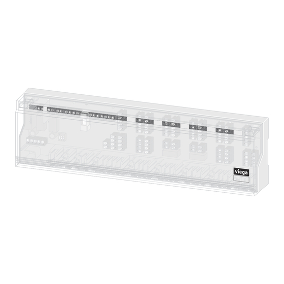
Product information 2.4.2 Overview and description of component Scope of delivery Fig. 1: Scope of delivery of the basic unit Holding clips Spacer Basic unit Dowel Screws 2.4.3 Technical data Operating voltage 230 V AC ±10%, 50 Hz Power consumption max. - Page 7 Switching capacity 2 A, 200 VA inductive Switch-on delay 2 min Overtravel time fixed 2 min Pump protective function every 14 days for one minute Connection diagram viega Mo Tu We Th Symbol Meaning Symbol Meaning Digital room thermostat Pump...
-
Page 8: Accessories
Product information Symbol Meaning Symbol Meaning Temperature limiter/dew point Change-over heating/cooling sensor Voltage source System clock Cooling Heating 2.4.4 Accessories Actuator Electrically operated actuator for opening and closing the control valve. Actuator "normally closed", 230 V – model 1249 Basic unit 230 V with pump module... - Page 9 Product information Room thermostat Transfers the necessary measurements to control the heating circuits to the basic unit via a cable connection. Room thermostat, analogue 230 V – model 1243 Room thermostat, digital 230 V with electronic weekly timer – model 1244 Basic unit 230 V with pump module...
-
Page 10: Handling
Handling Handling Transport and storage Observe the following with transport and storage: Avoid heavy blows and vibrations. Store components in a clean and dry place. Do not remove the components from the packaging until immedi‐ ately before use. NOTICE! Replace defective components, do not repair. Preconditions for mounting Provide a 230 V mains connection on site close to the heating circuit manifold for operation of the basic unit. -
Page 11: Mounting The Basic Unit
Handling 3.3.2 Mounting the basic unit Mounting preparation The manifold and actuators have been mounted. The power supply for the basic unit has been prepared. The room thermostats have been mounted and connected. Required tools and materials: Power drill Masonry drill Ø 6 mm or metal drill Ø 3 mm for installation on the dis‐ tributor cabinet rear panel screwdriver Two plugs 6 x 30 mm and screws for wall installation (scope of... -
Page 12: Commissioning
Handling Assembly on top-hat rail (not included in the scope of delivery) ▶ Fasten the two holding clips (scope of delivery) at the rear of the base station. ▶ Mount the top-hat rail to the wall. ▶ Use the holding clips to fasten the base station to the top-hat rail. Commissioning Connecting components Connect all external components such as actuators or... -
Page 13: Care Tips
Handling Connect the device to the Requirements: mains A 230 V mains connection is available on site. The connection cable is de-energised. ▶ Connect the 230 V mains connection cable to the labelled terminals on the basic unit, see connection diagram. NOTICE! Use a cable with a cross-section of 1.5 mm The basic unit is connected. -
Page 14: Disposal
Handling Disposal Separate the product and packaging materials (e. g. paper, metal, plastic or non-ferrous metals) and dispose of in accordance with valid national legal requirements. Electronic components and batteries must not be put in the domestic waste but must be disposed of appropriately in conformity with the applicable directives, see Ä... - Page 15 Viega GmbH & Co. KG service-technik@viega.de viega.com INT • 2023-01 • VPN170386...
Need help?
Do you have a question about the 1246.1 and is the answer not in the manual?
Questions and answers