
Related Manuals for Viega 1247.4


Summary of Contents for Viega 1247.4
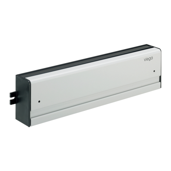
- Page 1 Basic unit 24 V with pump module Instructions for Use for Fonterra radiant heating and cooling, max. 6 room thermo- stats, max. 12 heating circuits Model Year built: 1247.4 from 01/2007 en_INT...
- Page 2 Basic unit 24 V with pump module 2 from 17...
-
Page 3: Table Of Contents
Table of contents Table of contents About these instructions for use Target groups About this translated version Product information Safety advice Intended use Product description 2.3.1 Functions 2.3.2 Overview and description of component 2.3.3 Technical data 2.3.4 Accessories Handling Transport and storage Preconditions for installation Assembly 3.3.1... -
Page 4: About These Instructions For Use
This restriction does not extend to possible operating instructions. The installation of Viega products must take place in accordance with the general rules of engineering and the Viega instructions for use. -
Page 5: Product Information
Product information 2 Product information Safety advice DANGER! Danger due to electrical current An electric shock can lead to burns and serious injury and even death. – Work on the electrics may only be carried out by trained electricians. – Switch off the mains voltage before carrying out work on electrical parts. -
Page 6: Overview And Description Of Component
Product information Features Simple plugging / clamping solution Connections per room thermostat (zone) – 2 actuators (standard) – 4 actuators (optional, max. 2 x) Connection for control of one circulation pump Connection for one external time switch Connection for room thermostats with time switch Optionally, you can transmit the signal of the room thermo- stat to two other actuators (terminal 2 and/or 5) at terminal 1 and/or 4. - Page 7 Fig. 3: Basic unit, terminal assignment 1 - fuse 2 - room thermostat terminals 3 - actuator terminals 4 - pump control terminals (only with model 1247.3 and 1247.4) 5 - external time switch terminals 6 - 24 V terminals CAUTION! Cable breakage due to tensile strain –...
-
Page 8: Technical Data
Product information 2.3.3 Technical data Operating voltage 24 V AC Max. wattage max. 50 W Switching voltage pump 230 V Switching current pump Fuse T 2A Max. no. of room thermostats Max. no. of actuators Heating programs - optional Protection class Degree of protection IP20 CE conformity... - Page 9 Product information Room thermostat Transmits the required measuring values to the basic unit for regulating the heating circuits via a cable connection: Room thermostat, analogue 24 V – model 1243.1 Fig. 5: Room thermostat analogue Room thermostat, digital 24 V with electronic week time switch – model 1243.4 Fig.
-
Page 10: Handling
Handling 3 Handling Transport and storage Observe the following with transport and storage: Avoid heavy blows and vibrations. Store components in a clean and dry place. Do not remove the components from the packaging until immedi- ately before use. NOTICE! Replace defective components, do not repair. -
Page 11: Mounting The Basic Unit
Handling 3.3.2 Mounting the basic unit Mounting preparation The manifold and actuators have been mounted. The power supply for the basic unit has been prepared. The room thermostats have been mounted and connected. Required tools and materials: Power drill Ø 6 mm masonry drill, or Ø 3 mm metal drill for mounting the basic unit to the rear of the manifold cabinet. -
Page 12: Commissioning
Handling Commissioning 3.4.1 Making the electrical connection Generating power supply with a power pack DANGER! Risk of electric shock An electric shock can lead to burns and serious injury and even death. – Work on the electrics may only be carried out by trained electricians. - Page 13 Handling Assigning two actuators to one RT Loosen the fixing screws and remove the cover of the casing. Break off the pre-cut cable inlet in the area of the connection ter- minal at the bottom of the casing. Insert the strain relief device provided by the customer. Connect the leads of the cable pursuant to the terminal diagram.
-
Page 14: Connecting The Room Thermostat
Handling 3.4.3 Connecting the room thermostat The cable is fed through the pre-cut openings in the casing. Strain relief devices matching the cables used must be provided by the customer. Loosen the fixing screws and remove the cover of the casing. Break off the pre-cut cable inlet in the area of the connection ter- minal at the bottom of the casing. -
Page 15: Connecting An External Time Switch
Handling 3.4.4 Connecting an external time switch Time switch with two switching signals – A or B. CAUTION! Risk of damage due to incompatible time switches The connection of an unsuitable time switch may result in malfunction and cause damage to the control. –... -
Page 16: Connecting The Pump
Handling 3.4.5 Connecting the pump Loosen the fixing screws and remove the cover of the casing. Break off the pre-cut cable inlet in the area of the connection ter- minal at the bottom of the casing. Insert the strain relief device provided by the customer. Bare the leads of the cable over a length of 10 mm or use cable sleeves, and connect them pursuant to the terminal diagram. -
Page 17: Care Tips
Handling Care tips The surfaces of the control elements are made of premium materials and require little care. When cleaning the elements, bear in mind that the devices are live. Make sure that no water gets into the casing. Care tips Wipe the surfaces down with a moist cloth.
Need help?
Do you have a question about the 1247.4 and is the answer not in the manual?
Questions and answers