
Related Manuals for Viega 1252.1


Summary of Contents for Viega 1252.1
- Page 1 Compact control station preset value Instructions for Use for Fonterra radiant heating and cooling, central regulation of the supply temperature of several manifolds Model Year built: 1252.1 from 01/2012 en_INT...
- Page 2 Compact control station preset value 2 from 11...
-
Page 3: Table Of Contents
Table of contents Table of contents About these instructions for use Target groups Labelling of notes About this translated version Product information Intended use 2.1.1 Areas of use Product description 2.2.1 Overview 2.2.2 Technical data Handling Assembly information 3.1.1 Installation dimensions 3.1.2 Change supply and return flow section Assembly... -
Page 4: About These Instructions For Use
This restriction does not extend to possible operating instructions. The installation of Viega products must take place in accordance with the general rules of engineering and the Viega instructions for use. -
Page 5: About This Translated Version
About these instructions for use About this translated version This instruction for use contains important information about the choice of product or system, assembly and commissioning as well as intended use and, if required, maintenance measures. The information about the products, their properties and application technology are based on the current standards in Europe (e. -
Page 6: Product Information
Product information 2 Product information Intended use 2.1.1 Areas of use Use the compact control station in heating systems where on the one hand their heat output takes place with a high supply temperature (e. g. radiators, heating ventilators or similar) and on the other hand through low-temperature heat surfaces (e. -
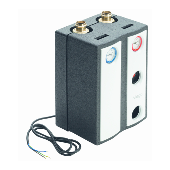
Page 7: Technical Data
Product information 2.2.2 Technical data Maximum permitted operating 95 °C temperature Minimum permitted operating -20 °C temperature Maximum permitted operating 1 MPa (10 bar) pressure Nominal heating capacity 15 kW with anti-freeze added, max. 40 % per cent by volume. With fluid temperatures below 20 °C, take potential condensation into consideration. -
Page 8: Handling
Handling 3 Handling Assembly information 3.1.1 Installation dimensions Fig. 2: Casing and connection dimensions Height (with insulation) approx. 344 mm (355 mm) Width with insulation approx. 250 mm Axis distance approx. 125 mm Connections G1½ x 28 Sanpress enclosed 3.1.2 Change supply and return flow section The compact control station factory-fitted with the supply on the right- hand side and the return flow on the left-hand side. - Page 9 Handling Remove the caps (B) as well as the connecting pipe (C). Loosen the pump screw fitting (D) as well as the return flow ball valve screw fitting (E). Rotate the pump with supply ball valve and return flow ball valve by 180°.
-
Page 10: Assembly
NOTICE! In the case of the compact control station model 1252.1 our settings are valid as opposed to the manufacturer's infor- mation. Manufacturer's documentation should be observed regarding maintenance and repairing faults. -
Page 11: Control
Handling Use the wall bracket to perforate the pre-formed slits in the rear part of the heat insulation from the front. Place the wall bracket to the wall (opening pointing up) and fasten it with dowel and screws. Clip in the rear part of the heat insulation. Insert the hexagonal pro- file of the ball valves in the hexagonal profile of the wall bracket.
Need help?
Do you have a question about the 1252.1 and is the answer not in the manual?
Questions and answers