Table of Contents
Advertisement
Advertisement
Table of Contents

Subscribe to Our Youtube Channel
Related Manuals for Autel Robotics EVO II RTK V3 Series


Summary of Contents for Autel Robotics EVO II RTK V3 Series
- Page 1 Aircraft User Manual V2.0.2 2024.03...
- Page 2 Copyright This manual is copyrighted by Autel Robotics Co., Ltd. with all rights reserved. Without prior written authorization from the company, no person (or entity) may copy, scan, store, distribute, reproduce, sell, transfer, or modify any part or all of this manual in any form for personal use or use by others.
- Page 3 Thank you for purchasing and using the EVO II RTK Series V3 aircraft (hereinafter referred to as "aircraft") from Autel Robotics. Relevant user documents for this product are provided in electronic form along with the product, and download links are provided in this manual. Before...
- Page 4 Inertia Measurement Unit Read Before Your First Flight To ensure safe use of the EVO II RTK Series V3 aircraft, Autel Robotics provides you with the following documents and relevant tutorial videos. Please scan the QR codes in this manual or use the provided links to access them.
- Page 5 Store the aircraft and its accessories out of the reach of children and pets. If you do not abide by the Safety Operation Guidelines, Autel Robotics shall not be responsible for any product damage or personal and property loss during use, and shall not provide any warranty service.
- Page 6 Robotics may not be able to analyze the causes of product damage or accidents and provide after-sales service. Using the EVO II RTK Series V3 aircraft of Autel Robotics involves certain safety risks. Do not allow minors to operate the aircraft.
- Page 7 Autel Robotics guarantees users who purchase products through its official authorized channels that: Under normal use, the Autel Robotics products you purchase will be free from material and workmanship defects during the warranty period. If you can provide a valid purchase receipt, the warranty period of this product is calculated from the midnight of the next day after you receive the product.
-
Page 8: Table Of Contents
Table of Contents Product Overview ........................1 Introduction ..........................1 What's In The Rugged Case ....................2 Product Acceptance Checklist ....................3 UAS Introduction ........................4 Flight Safety ..........................8 Legal Use Guidelines ......................8 Chinese Mainland ......................8 The U.S.......................... 9 Canada .......................... - Page 9 IMU Calibration ....................... 27 Gimbal Auto Calibration ..................30 Emergency Propeller Stop in Flight ................. 30 Direct Remote Identification .................... 31 Standard Flight Operation Process ................. 31 Pre-flight Inspection Checklist ................31 Basic Flight Procedure .................... 32 List of Safeguard ........................ 33 Aircraft ..........................
- Page 10 Checking the Battery Level of the Remote Controller ............ 67 Charging the Remote Controller ..................68 Adjusting the Antenna Position of the Remote Controller ..........69 Remote Controller System Interfaces ................70 Remote Controller Main Interface ................70 Shortcut Menu ......................73 Frequency Pairing With the Remote Controller ...............
- Page 11 Map Interface ........................101 Camera Interface ....................... 103 Mission ..........................104 Firmware Updates and Maintenance ................106 Aircraft and Remote Controller Firmware Updates ............106 Aircraft parts maintenance ....................107 Troubleshooting Guide ..................... 108 Appendix A Product Specifications ....................111 A.1 Aircraft ..........................
-
Page 13: Product Overview
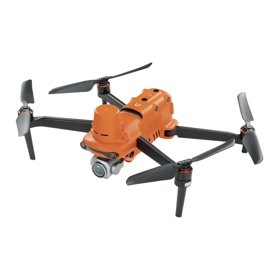
Chapter 1 Product Overview Product Overview Introduction The EVO II RTK Series V3 aircraft is a lightweight aircraft, integrated with a visual sensing system of 12 visual sensors for six directions, and has an omnidirectional obstacle avoidance capability. With an excellent power management system, the aircraft can reach a flight time of up to 36 minutes. -
Page 14: What's In The Rugged Case
Chapter 1 Product Overview If multiple aircraft are flying in an area at the same time, please keep an appropriate air distance to avoid any accidents. What's In The Rugged Case Item Note Multi-Charger Comes with a battery multi-charger. Smart Battery Comes with 2 spare batteries. -
Page 15: Product Acceptance Checklist
After unboxing the product, please check whether the actual items match the items described in the following packing list and carefully inspect the appearance of the aircraft and all accessories. If anything missing or damage is found, please contact Autel Robotics After-Sales Support or authorized dealers promptly. -
Page 16: Uas Introduction
Item Product Info Manufacturer Note Includes RTK Max. weight: 1237 g Module, EVO II Pro RTK Max. Dimension: 457×558×143mm Autel Robotics propellers, V3 Aircraft EAN: 6924991126874 battery, and a UPC: 889520206877 gimbal. Max. weight: 1250 g Includes RTK EVO II Dual 640T Max. - Page 17 “3.11 Extension Interface ” in Chapter 3. All the above components have passed Autel Robotics safety and compatibility tests, users can purchase and use accordingly. In case of adding any payload before flight, please evaluate the mounting weight reasonably.
- Page 18 Note System Max. weight: 1194 g Includes 2 Max. Dimension: Autel Smart command 269×302×87 mm Android 11 Autel Robotics Controller V3 sticks and 2 EAN: 6924991126263 antennas. UPC: 889520206266 Table 1-4 Firmware and Software version explanation Item Release Version Note...
- Page 19 Chapter 1 Product Overview Maxitools 2.45 System Software Google Pinyin Input 4.5.2.193126728-arm64-v8a System Software Android Keyboard System Software (AOSP) The pre-installed Apps mentioned are the basic application for the remote controller. Users also have the option to install third-party software if desired.
-
Page 20: Flight Safety
The EVO II RTK Series V3 aircraft is a light unmanned aircraft, and the operation of this product by individuals under the age of 18 is prohibited by Autel Robotics. It is recommended to read the "Interim Regulations on the Management of Unmanned Aerial Vehicle Flights"... -
Page 21: The U.s
Chapter 2 Flight Safety The U.S. Before using a drone, please complete the real-name registration on the FAA website (https://faadronezone-access.faa.gov/#/) (registrants must be 13 years old or above). Failure to do so may result in regulatory and criminal penalties. ... -
Page 22: Other Countries And Regions
Chapter 2 Flight Safety 2. Maintain a horizontal safety distance of at least 30 meters from any non-involved persons, which can be reduced to 5 meters in low-speed mode. 3. Maintain a flight altitude within 120 meters above the ground. ... -
Page 23: Flight Environment Requirements
Chapter 2 Flight Safety Prohibit the use of the aircraft at large event venues, including but not limited to sports stadiums and concerts. Avoid flying in airspace exceeding the regulated altitude. Do not use the aircraft to carry any illegal hazardous materials. ... -
Page 24: Declaration Of Maximum Take-Off Mass
Chapter 2 Flight Safety Exercise caution when flying near electromagnetic interference sources and continuously monitor and assess the stability of the remote controller's video transmission signal and image. Common sources of electromagnetic interference include, but are not limited to, high-voltage transmission lines, high-voltage substations, mobile communication base stations, and TV broadcast signal towers. -
Page 25: Obstacle Avoidance System
Chapter 2 Flight Safety Recommended mounted area (bottom view) Recommended mounted location (not affecting the observation range) Note To keep the vision and the performance of the aircraft solid, it is recommended that when users are mounting payload, the mounting point should be located at the center line of the aircraft and should not be beyond the area bracketed in the fig 2-1. -
Page 26: Visual Positioning Function
Chapter 2 Flight Safety fuselage with the "dual pinhole lens" structure, for achieving omni-directional visual obstacle avoidance for the aircraft. Aircraft Visual Perception Range When using the aircraft for flight, avoid obstructing the lenses of the visual perception system. Doing so may impact the performance of the aircraft's visual obstacle avoidance and could lead to flight accidents. -
Page 27: Visual Obstacle Avoidance Function
Chapter 2 Flight Safety If you lack extensive flight experience, try to avoid flying beyond visual range. When relying on visual localization for flight, avoid flying near surfaces such as water or snowy areas with mirror-like reflections. In poor GNSS signal conditions, ensure the aircraft is flying in well-lit environments with clear object surface textures. -
Page 28: Auto Return Home
Chapter 2 Flight Safety Extremely dark surfaces (light intensity less than 15 lux) or extremely bright surfaces. Small obstacles (such as wires, power lines, branches, etc.). Dirty lenses (such as water droplets, fingerprints, etc.). Scenes with low visibility (such as heavy fog, heavy snow, etc.). ... -
Page 29: Manual Activation Of Auto Return Home
Chapter 2 Flight Safety Manual Activation of Auto Return Home During flight, users can manually activate the auto return home by long-pressing the return home button " " on the remote controller for 2 seconds. Low Battery Activation of Auto Return Home During flight, to prevent unnecessary risks due to insufficient battery power, the aircraft will intelligently assess whether the current battery level is sufficient based on the aircraft's current position. -
Page 30: Behavior Activation Of Auto Return Home
Chapter 2 Flight Safety Behavior Activation of Auto Return Home During the execution of a flight mission, setting the completion action as "Go Home" will activate the auto return home after completing the mission. Setting the loss of connection action as "Go Home"... -
Page 31: Auto Return Home Obstacle Avoidance Process
Chapter 2 Flight Safety Auto Return Home Obstacle Avoidance Process When the obstacle avoidance system is enabled and the lighting conditions allow the visual perception system to function, the aircraft will implement obstacle avoidance during the auto return home process as follows: ... -
Page 32: Rebuilding Of The C2 Link
Geofence System Autel Robotics has developed a geofence system for its drones to ensure safe and legal flights. This system can dynamically update airspace restriction information worldwide. In different restricted zones, the drone's flight functions will be restricted to varying degrees. The geofence system also supports unlocking restricted zones. -
Page 33: Restricted Zones
All information should be based on local laws and regulations. For temporary airspace control, Autel Robotics will promptly obtain the corresponding regulatory notices and upload the relevant airspace restriction information to the geofencing system. - Page 34 Chapter 2 Flight Safety Distance Limits" in this chapter and “6.4 Settings Interface” in Chapter 6. Factory-installed in the geofence system, regularly updated. Factory-installed in the geofence system, regularly updated. Update Method: The remote controller automatically fetches Warning Zone the warning zone update information and pushes it to the (Displayed in yellow on the aircraft.
-
Page 35: Import Ugz
Chapter 2 Flight Safety When the aircraft not lifted flies towards the no-fly zone from the outside: When the aircraft touches the boundary of the buffer zone, Buffer zone of the no-fly the Autel Explorer App will display a warning alert says zone "Approaching a Flight Restricted Area"... -
Page 36: Unlocking No-Fly Zones
5. Aircraft S/N (Serial number): Multiple serial numbers can be applied at once. 6. Autel account of UAS operator: Multiple accounts can be applied at once. Log in to the official website of Autel Robotics at www.autelrobotics.com/service/noflight/, enter the relevant information, and complete the waiver application. -
Page 37: Aircraft Calibration
Chapter 2 Flight Safety Altitude and Distance Limitation Diagram In the Autel Explorer App, the allowable range for altitude restriction is 30 ~ 800 m, and the allowable range for distance restriction is 30 ~ 5000 m. During actual flight, the set maximum altitude limit should not exceed the altitude restricted by local laws and regulations, such as the maximum flight altitude of aircraft in mainland China, the United States, the European Union and other countries and regions should not exceed 120 meters... - Page 38 Chapter 2 Flight Safety Please stay away from strong magnetic field areas or large pieces of metal during calibration, such as magnetic ore, parking lots, construction areas with underground steel bars, near underground or overhead power transmission lines, etc. ...
-
Page 39: Imu Calibration
Chapter 2 Flight Safety Hold onto the aircraft to keep it in a vertical position with the nose pointing upward. Rotate horizontally 360° until the rear arm light of the aircraft turns green and blinks Hold onto the aircraft, positioning the nose to the left and the side facing downward. - Page 40 Chapter 2 Flight Safety The gimbal will be inactive during the IMU calibration process. Table 2-5 IMU Calibration Step Operation Diagram After turning on the aircraft and remote control, tap " " > "Flight Control" > "IMU Calibration" > "Start Calibration"...
- Page 41 Chapter 2 Flight Safety Place the left side of the aircraft flat on the ground until the App prompts you to proceed to the next step. Place the right side of the aircraft flat on the ground until the App prompts you to proceed to the next step.
-
Page 42: Gimbal Auto Calibration
Chapter 2 Flight Safety If the calibration fails, the App will prompt you. In this case, you should repeat the above steps. Gimbal Auto Calibration The gimbal is calibrated during the manufacturing of the aircraft and typically does not require user-initiated auto-calibration. -
Page 43: Direct Remote Identification
If the propellers are stopped when the aircraft has a certain initial velocity, the aircraft will follow a parabolic trajectory during free fall. Do not stop the propellers in this unpredictable scenario. After completing the forced landing, please contact Autel Robotics promptly for inspection of the power system. Direct Remote Identification The Direct Remote Identification (DRI) system allows the registration number of the unmanned aircraft system operator (Remote ID) to be uploaded to the system. -
Page 44: Basic Flight Procedure
Chapter 2 Flight Safety Ensure the aircraft propellers are securely installed without damage or deformation, the motor and propeller surfaces are clean and free of foreign objects, and the propellers and arms are in fully extended positions. Ensure there are no foreign objects, dirt, or fingerprints on the lenses of the aircraft's visual cameras, gimbal camera, or supplementary lights, and they are not obstructed by mounts or other accessories on the aircraft. -
Page 45: List Of Safeguard
Chapter 2 Flight Safety List of Safeguard Before flight, please know the following safeguard information, which helps you handle abnormal situations in a correct and safe way. Table 2-7 List of Safeguard Safety Function Refer To Auto Return Home “2.7 Auto Return Home”... -
Page 46: Aircraft
Make sure that the remote controller is connected to the Internet before starting the activation process. Otherwise, activation may fail. If activation fails, please contact Autel Robotics After-Sales Support for assistance. For how to pair the aircraft with the remote controller, please refer to “4.9 Frequency... - Page 47 Chapter 3 Aircraft Motor Used to drive the propeller to rotate. Front Arm Light Used to identify the nose direction of the aircraft. Used to support the aircraft to avoid damage to the bottom of Landing Gear the fuselage. Forward Visual Used to sense the obstacles ahead and avoid the aircraft from Sensing System colliding with them.
- Page 48 Chapter 3 Aircraft Aircraft Left View Table 3-3 Aircraft Left View Details Name Description Left Visual Sensing Used to sense the obstacles in the left and avoid the aircraft System from colliding with them. microSD Card Slot For inserting a microSD card. Aircraft Right View Table 3-4 Aircraft Right View Details Name...
- Page 49 Chapter 3 Aircraft The USB-C interface of the aircraft is not available for charging. Please do not connect a charger to it. For aircraft charging, refer to “5.3.4 Charging the Smart Battery” in Chapter 5. Aircraft Top View Table 3-5 Aircraft Top View Details Name Description Upward Visual...
-
Page 50: Propeller
Chapter 3 Aircraft Table 3-6 Aircraft Down View Details Name Description Used to sense obstacles beneath the aircraft, avoiding Ultrasonic Sensor collisions with them. An LED auxiliary light. It is used to enhance the ambient brightness of the landing area during the landing process, Auxiliary Light improve downward visual sensing performance, and ensure the safe landing of the aircraft. - Page 51 Propellers cannot be installed on the wrong propeller mounts. Please carefully distinguish between propellers and mounts. Autel Robotics provides two spares of propellers for each aircraft (with models CW and CCW, respectively). Please refer to the “Packing List” and packaging for details.
-
Page 52: Storing Propellers
Before each flight, make sure that all propellers are mounted correctly and securely. Please use the propellers provided by Autel Robotics. Do not mix propellers of different models. -
Page 53: Arm Light
Chapter 3 Aircraft Arm Light After takeoff, the four arms of the aircraft each have an LED indicator at the end. The front arm light will periodically flash to assist users in identifying the front direction of the aircraft. The rear arm lights will display the current status of the aircraft. -
Page 54: Auxiliary Bottom Light
Chapter 3 Aircraft R–Always On IMU Abnormal RY–Alternating Slow Flashing Magnetometer Abnormal/ Calibration Required Slow flashing: flashes once every 2s (0.5s on/1.5s off). Fast flashing: flashes twice every 1s. Ultra-fast flashing: flashes 5 times per second. When the aircraft performs power-on self-test and any of the following situations occurs, the following strategies will be implemented to ensure flight safety. -
Page 55: Camera
Chapter 3 Aircraft For how to turn the auxiliary bottom lights on or off, please refer to “6.4 Settings Interface” in Chapter 6. When the auxiliary bottom lights are set to “AUTO”, they will turn on automatically at an altitude of 3 meters above the ground when the aircraft is landing and the ambient light is insufficient, and they will turn off automatically after a successful landing. -
Page 56: Camera Operations
Chapter 3 Aircraft The infrared thermal imaging camera of EVO II 640T RTK V3 is used for radiometric measurement and night vision, which can Infrared Thermal monitor the temperature distribution of the measured target in Imaging Camera real time, so as to judge the state of the target. Radiometric temperature range: -20°C~+150°C (high gain mode) and 0°C + 550°C (low gain mode). - Page 57 Chapter 3 Aircraft Gimbal Structure Please be aware that, except for differences in camera layout, the gimbal structure of EVO II Dual 640T RTK V3 aircraft and EVO II Pro RTK V3 aircraft is similar. Table 3-12 Gimbal Structure Details name Description MCU Installation...
-
Page 58: Gimbal Mechanical Rotation Range
Chapter 3 Aircraft Gimbal Mechanical Rotation Range The mechanical rotation ranges of the pitch, yaw, and roll axes of the gimbal are shown below. Table 3-13 Mechanical Rotation Range of the Gimbal of the EVO II RTK Series V3 Aircraft ... -
Page 59: Replacing The Gimbal
Please use the gimbal model specified by Autel Robotics for replacement. Incompatible gimbals may cause damage to the aircraft. Do not attempt to remove or mount the gimbal when it is powered on. Wait for 15 seconds after powering off the aircraft (the internal capacitor is fully discharged) before removing or mounting the gimbal. - Page 60 Chapter 3 Aircraft When removing the gimbal, do not forcefully pull the gimbal out, as this may cause damage to the gimbal or camera. You should hold the gimbal dampener mount to remove the gimbal. Removing the Gimbal Mounting the Gimbal 1.
-
Page 61: Flight Control System
Chapter 3 Aircraft Flight Control System EVO II RTK Series V3 aircraft achieves stable and convenient flight control through its built-in intelligent flight control system. The system supports a number of advanced functions, including auto-return, failsafe, visual positioning system, etc. Table 3-14 Flight Control System Module Description... -
Page 62: Flight Modes
Chapter 3 Aircraft when there is no GNSS signal and visual positioning failure at the same time, the ATTI mode will be activated. In this mode, the obstacle avoidance system is disabled, and the aircraft only controls the altitude through the barometer. ... -
Page 63: Intelligent Flight Function
Chapter 3 Aircraft Intelligent Flight Function Accurate Landing The accurate landing function uses the downward binocular visual sensing system of the aircraft to record the information at its take-off point. When the aircraft is returning to the home point or landing, vision algorithms are used to calculate the distance between the aircraft and the take- off point in real time so as to make sure that the aircraft successfully lands at the take-off point. -
Page 64: Connecting To Pc/Mac
Chapter 3 Aircraft The aircraft has built-in 8 GB storage space, with approximately 6 GB available due to system firmware and app updates. It is recommended that you prioritize using an external microSD card for storing the image data collected during flight to avoid running out of internal storage space, which will affect the flight safety of the aircraft. - Page 65 The RTK module is the standard configuration for the EVO II RTK Series V3 aircraft. Loudspeakers, spotlights, and strobes (beacons) are optional configurations and needs to be purchased separately. If needed, please contact Autel Robotics official or authorized dealers.
-
Page 66: The Noise Description
Chapter 3 Aircraft Part Number (UPC) 889520012058 Manufacturer Autel Robotics Maximum Mount Dimension 38×72×34mm Maximum Mount Weight 19.5g Aircraft firmware version: V1.1.55 Software Version Requirement Remote controller version: V1.3.9.8 Autel Explorer version: 3.1.63 Mount Info RTK Module Part Number (EAN) -
Page 67: Autel Skylink Image Transmission Function
Chapter 3 Aircraft A-weighted sound power level of EVO II RTK Series V3 aircraft A-weighted sound pressure level Measurement results for the EVO II RTK Series V3 aircraft, in accordance with the requirements of GB 42590-2023 in Chinese mainland, are provided below: Table 3-18 Noise Measurements Results (normalized to 1 m from the aircraft) Observation Points Hover... - Page 68 Chapter 3 Aircraft The transmission data is based on the remote controller and comes from test data, and the test environment and conditions are different, and the data may be different. The transmission range is provided for reference only, and during actual use, it is important to monitor the quality of the video transmission signal continuously.
- Page 69 Table 3-20 Supported list of aircraft ground control equipment Control Device Information Autel Smart Controller V3 Part Number (EAN) 6924991126263 Part Number (UPC) 889520206266 Manufacturer Autel Robotics Control Software Autel Explorer App Software Version Requirement V1.0.0.0 or higher Supplementary Information Standard configuration...
- Page 70 The Autel Smart Controller V3 is included as a standard item in the aircraft package, and Autel Robotics also provides retail packaging for customers to choose independently. The Autel Smart Controller V3 is available in multiple retail versions. Only the remote controller that has the Autel Explorer App installed supports the control of the EVO II RTK Series V3 aircraft.
-
Page 71: Remote Controller
Chapter 4 Remote Controller Remote Controller Introduction The Autel Smart Controller V3 is installed with the Autel Explorer App by default, allowing you to operate and set the aircraft and the gimbal camera and transmit high-definition videos from the gimbal camera in real time. It offers a maximum communication distance of 15 kilometers. ... - Page 72 Chapter 4 Remote Controller Video Recording Tap to start/end recording videos. Button Use the Autel Explorer App to customize the key function. For Key C1 more information, please refer to “6.4 Settings Interface” in Chapter 6. For heat dissipation of the remote controller. When using it, Air Outlet please pay attention to whether there are foreign objects blocking the air outlet.
- Page 73 Chapter 4 Remote Controller Remote Controller Front View Table 4-2 Remote Controller Front View Details Name Description Transmits the control signals of the remote controller and Antenna receives the image transmission information of the aircraft. Battery Level Displays the remaining battery level of the remote controller. Indicator Receives information from an external audio source near the Audio Input...
-
Page 74: Communication Frequency Bands
Chapter 4 Remote Controller Remote Controller Rear View Table 4-3 Remote Controller Rear View Details Name Description Speaker Plays sound to indicate the status of the aircraft. Optional accessory. Used to prevent external damage such as Protective Cover collision and abrasion of the remote controller. Lower Hook Used to connect and fix the remote controller strap. - Page 75 Chapter 4 Remote Controller After the aircraft is paired with the remote controller, the frequency bands between them will be automatically controlled by the Autel Explorer App based on the geographical information of the aircraft. This is to ensure compliance with local regulations regarding frequency bands.
-
Page 76: Installing The Remote Controller Lanyard
Chapter 4 Remote Controller Table 4-5 Global Certified Frequency Bands (Wi-Fi) Operating Frequency Details Certified Countries & Regions Chinese Mainland Taiwan, China United States Canada 2.4G 802.11b/g/n EU (2400 – 2483.5 MHz) United Kingdom ... -
Page 77: Installing/Storing Command Sticks
Chapter 4 Remote Controller Install the Remote Controller Lanyard (As Required) Installing/Storing Command Sticks The Autel Smart Controller V3 features removable command sticks, which effectively reduce storage space and enable easy carrying and transportation. Installing command sticks There is a command stick storage slot above the mental handle at the back of the controller. Rotate counterclockwise to remove the two command sticks and then rotate them clockwise to install them separately on the remote controller. -
Page 78: Turning The Remote Controller On/Off
Chapter 4 Remote Controller This can prevent you from accidentally touching the command sticks, causing damage to the sticks or unintended startup of the aircraft. Turning the Remote Controller On/Off Turning the Remote Controller On Press and hold the power button at the top of the remote controller for 3 seconds until the controller emits a "beep"... -
Page 79: Checking The Battery Level Of The Remote Controller
Chapter 4 Remote Controller Turning the Remote Controller Off When the remote controller is on, you can press and hold the power button at the top of the remote controller for 4 seconds to forcibly turn it off. Checking the Battery Level of the Remote Controller When the remote controller is off, short press the power button of the remote controller for 1 second, and the battery level indicator will display the battery level of the remote controller. -
Page 80: Charging The Remote Controller
USB-C to USB-C cable and connect the plug of the charger to an AC power supply (100- 240 V~ 50/60 Hz). Use the RC charger to charge the remote controller Please use the official charger provided by Autel Robotics to charge the remote controller. Using third-party chargers may damage the battery of the remote controller. -
Page 81: Adjusting The Antenna Position Of The Remote Controller
Chapter 4 Remote Controller After charging is complete, please disconnect the remote controller from the charging device promptly. It is recommended to fully charge the remote controller battery before the aircraft takes off. Generally, it takes about 120 minutes to fully charge the aircraft battery, but the charging time is related to the remaining battery level. -
Page 82: Remote Controller System Interfaces
Chapter 4 Remote Controller Extend the antenna Remote Controller System Interfaces Remote Controller Main Interface After the remote controller is turned on, it enters the main interface of the Autel Explorer App by default. In the main interface of the Autel Explorer App, slide down from the top of the touch screen or slide up from the bottom of the touch screen to display the system status notification bar and navigation keys, and tap the "Home"... - Page 83 Chapter 4 Remote Controller Remote Controller Main Interface Table 4-7 Remote Controller Main Interface Details Name Description Time Indicates the current system time. Battery Status Indicates the current battery status of the remote controller. Indicates that Wi-Fi is currently connected. If not connected, the icon is not displayed.
- Page 84 Chapter 4 Remote Controller sound, storage, location information, security, language, gestures, date and time, device name, etc. The app is installed in the system by default. Tap it to manage Files the files saved in the current system. Google Chrome. The app is installed in the system by default. Chrome When the remote controller is connected to the Internet, you can use it to browse web pages and access Internet resources.
-
Page 85: Shortcut Menu
Chapter 4 Remote Controller Settings √ Android 11 MaxiTools √ 2.45 Android 11 Google Pinyin √ 4.5.2.193126728-arm64-v8a Android 11 Input Android √ Android 11 Keyboard (AOSP) com.android.prov √ Android 11 ision Quickstep √ Android 11 Please be aware that the factory version of the Autel Explorer App may vary depending on subsequent function upgrades. -
Page 86: Frequency Pairing With The Remote Controller
Chapter 4 Remote Controller Table 4-9 Shortcut Menu Details Name Description Screen Brightness Drag the slider to adjust the screen brightness. Adjustment Shortcut Edit Tap to arrange the layout of the Menu Tap the icon to enable or disable the Wi-Fi function. Long press Wi-Fi it to enter WLAN settings and select the wireless network to be connected. -
Page 87: Using Combination Buttons (For Forced Frequency Pairing)
Chapter 4 Remote Controller Table 4-10 Frequency Pairing Process in the Autel Explorer App Step Operation Diagram Turn on the remote controller and the aircraft. After entering the main interface of the Autel Explorer App, tap “ ” in the upper-right corner, select “Remote Control”, and then tap "Remote Control Matching". -
Page 88: Selecting Stick Mode
Chapter 4 Remote Controller 1. Press and hold the power button and the take-off/return-to-home button of the remote controller at the same time until the battery level indicator of the remote controller flashes quickly, which indicates that the remote controller has entered the forced frequency pairing state. - Page 89 Chapter 4 Remote Controller Mode 2 Mode 2 Table 4-12 Mode 2 Details Stick Move Up/Down Move Left/Right Left Controls the ascent and descent of Command Controls the heading of the aircraft the aircraft Stick Right Controls the forward and backward Controls the left or right movement Command movement of the aircraft...
-
Page 90: Setting Stick Mode
Chapter 4 Remote Controller Right Controls the ascent and descent of Command Controls the heading of the aircraft the aircraft Stick Do not hand over the remote controller to persons who have not learned how to use the remote controller. ... - Page 91 Chapter 4 Remote Controller The larger the degree of the stick movement, the greater the rotational angular velocity of the aircraft. Right Command The up-and-down direction of the right stick Stick is the pitch stick, which is used to control Move Up or the flight of the aircraft in the forward and Down...
-
Page 92: Starting/Stopping The Aircraft Motor
Chapter 4 Remote Controller Starting/Stopping the Aircraft Motor Table 4-15 Start/Stop the Aircraft Motor Process Stick Operation Description Power on the aircraft, and the aircraft will automatically perform a self-check. Then Start the aircraft motor simultaneously move the left and right when the aircraft is sticks inward or outward for 2 seconds, as powered on... -
Page 93: Take-Off/Return-To-Home Button And Pause Button
Chapter 4 Remote Controller Custom Keys C1 and C2 Table 4-16 C1 and C2 Customizable Settings Function Description Press to trigger: turn on/off the visual sensing system. Visual Obstacle When this function is enabled, the aircraft will automatically Avoidance On/Off hover when it detects obstacles in the field of view. -
Page 94: Turning On/Off The Remote Controller Prompt Sound
Chapter 4 Remote Controller To manually activate the auto-return function, press and hold the take-off/return-to-home button “ ” on the remote controller for 2 seconds until the remote controller emits a "beep" sound. Upon receiving the command, the aircraft will automatically return and land at the preset home point. -
Page 95: Calibrating The Remote Controller
Chapter 4 Remote Controller You can access the system settings app from the main interface of the remote controller, and then drag the volume slider in “Sound” to adjust the media volume and notification volume separately. Calibrating the Remote Controller If the remote controller is abnormal, it is recommended to calibrate it, as shown below. -
Page 96: Hdmi Screen Output
Chapter 4 Remote Controller HDMI Screen Output The remote controller is equipped with an HDMI interface. The interface allows you to output the real-time screen of the remote controller to supported digital devices such as display screen. -
Page 97: Smart Battery
Chapter 5 Smart Battery Smart Battery Battery Introduction The EVO II RTK Series V3 aircraft comes standard with the XE3_7100_1155 smart battery (hereafter referred to as smart battery) as the power battery. This battery is a rechargeable lithium-ion polymer (LiPo) battery and features high energy density and capacity. The smart battery can be charged with an XA3_1320 battery charger. -
Page 98: Smart Battery Functions
Chapter 5 Smart Battery Smart Battery Functions The smart battery has the following functions: Battery Level Display The smart battery has a built-in battery level indicator, which shows the current battery level of the smart battery. Communication The aircraft can obtain real-time battery information, such as voltage, current, battery level, and battery temperature, through the communication interface on the smart battery. -
Page 99: Smart Battery Usage
Chapter 5 Smart Battery Short Circuit Protection Once a short circuit is detected, the power supply of the smart battery will be cut off to protect the battery. Before using the smart battery, please carefully read and strictly follow the requirements in this Manual, “Battery Safety Operation Guidelines”, and “Disclaimer”, and those on the battery's surface sticker. -
Page 100: Turning On/Off The Smart Battery
Chapter 5 Smart Battery Slowly insert the smart battery into the battery compartment on the aircraft fuselage, and you will hear a clicking sound when the battery is in place. If the smart battery is not installed properly, it may cause the battery to fall off during the flight, damage the aircraft, or even cause personal injury. -
Page 101: Checking Battery Level
Chapter 5 Smart Battery Turning Off the Smart Battery When the smart battery is turned on, press and hold the power button for 3 seconds to turn off the battery. Turn On or Off the Smart Battery If the smart battery is not installed in the aircraft, it is not recommended to turn on/off the battery, and attention should be paid to insulation protection at the battery connector. -
Page 102: Charging The Smart Battery
Chapter 5 Smart Battery Table 5-4 Battery Level Indicator Status (While Not Charging) : Green light is always on : Green light blinking : Off After the aircraft is connected to the remote controller, you can check the current smart battery level of the aircraft in the top status bar or on the "Aircraft Battery"... - Page 103 Modifying the official smart battery or charging device provided by Autel Robotics is prohibited. Only use the battery and charging device provided by Autel Robotics. Autel Robotics is not responsible for any consequences, such as battery accidents and flight failure, caused by the use of third-party batteries or charging devices.
-
Page 104: Storing And Transporting The Smart Battery
Chapter 5 Smart Battery : Indicator light blinking : Off Storing and Transporting the Smart Battery When storing the smart battery, keep the battery away from water or heat sources and store it in a dry, well-ventilated environment at room temperature. Ideal storage conditions: The battery level is at around 60%, the ambient temperature is between 22°C to 28°C, and the ambient humidity is 65%±20% RH. -
Page 105: Standard Charging And Discharging Process
Chapter 5 Smart Battery 1. Perform a standard charge and discharge operation on the smart battery. 2. Insert the smart battery into the aircraft and turn on the power. Check the battery information through the Autel Explorer App, whether the voltage difference between the battery cells is less than 0.1 V, and whether the battery firmware is up to date. -
Page 106: Autel Explorer App
Autel Explorer App Software introduction Autel Explorer App is the flight software developed by Autel Robotics for industry applications. The software integrates a variety of professional functions, which is easy to improve efficiency. Through a variety of built-in intelligent flight functions, the aircraft can be highly intelligent operation, enabling industrial applications. -
Page 107: Status Bar
Description Personal Account Register or log in to an Autel account to use the relevant cloud Center services provided by Autel Robotics. After entering this mode (Intelligent Photo), you can choose following mission scenarios: Manual flight (default), Panorama, “Camera” mode Hyperlapse, Orbit Hyperlapse, Dynamic Track, Smart Orbit, Orbit. -
Page 108: Settings Interface
Chapter 6 Autel Explorer App 3. When not connected to the vehicle, the remote control signal is displayed. 1. Displays the GNSS location signal status of the current vehicle. 2. Tap the icon to display the specific signal state 3. When the vehicle cannot obtain GNSS signal, GNSS Signal status and the number of star searches. - Page 109 Chapter 6 Autel Explorer App Settings Interface Table 6-3 Details of the Settings Interface of the Autel Explorer App Module Setting Item You can turn on or off the novice mode. Set the return altitude of the aircraft, the setting range is 25-800 meters.
- Page 110 Chapter 6 Autel Explorer App Adjust control sensitivity. The aircraft RTK positioning function can be turned on or off. RTK* Set the way to receive RTK signals. You can turn on or off the RTK service and configure the RTK account and password.
-
Page 111: Operating Mode
Chapter 6 Autel Explorer App The voice broadcast function can be turned on or off. The obstacle warning sound can be turned on or off. The "Don't show again" pop-up box can be reset. The Remote ID function can be turned on/off. ... - Page 112 Chapter 6 Autel Explorer App Oblique Recording Slope Before selecting "Mission" mode, please ensure that the aircraft's GNSS signal is good, otherwise the aircraft will not be able to take off and perform the mission. Before flying in “Manual Flight” mission scenario, please ensure that the pilot has the corresponding UA pilot certificate and make sure that the visibility is great.
-
Page 113: Map Interface
Chapter 6 Autel Explorer App the Mission scenario selection page of the "Mission" mode Map Interface Users can plan routes or observe aircraft flight trajectories on the map interface. In "Camera" and "Mission" modes, the map interface and camera interface can be switched back and forth. ... - Page 114 Chapter 6 Autel Explorer App Map Interface (In “Camera” Mode) Table 6-5 Details of the Map Interface Name Description Tap this icon to switch the style of displaying the device's Orientation display orientation information, and support real-time display of the aircraft's flight altitude, flight distance, and flight speed.
-
Page 115: Camera Interface
Chapter 6 Autel Explorer App Camera Interface Users can freely switch between visible light lens and infrared lens display on the camera interface, and support switching photo and video functions and starting live broadcast. Camera Interface (Visible Light) Table 6-6 Details of the Camera Interface Name Description live streaming... -
Page 116: Mission
Chapter 6 Autel Explorer App When selecting the recording working mode, tap the recording button to start recording; tap the recording button again to end recording. If the aircraft has an infrared lens (i.e. EVO II Dual 640T RTK V3), when the lens is switched to the infrared lens, the infrared temperature measurement function can be turned on: pointing temperature measurement, area temperature measurement, temperature alarm, picture-in-picture mode, etc. - Page 117 Chapter 6 Autel Explorer App Waypoint Mission Page After completing the mission editing, tap the " " icon on the right side of the page to perform a pre-flight check. After confirming that it is normal, you can perform the automatic flight mission.
-
Page 118: Firmware Updates And Maintenance
Chapter 7 Firmware Updates and Maintenance Firmware Updates and Maintenance In order to optimize aircraft performance, Autel Robotics will update relevant firmware when necessary. You can download a unified firmware upgrade package from the official website, which contains the latest versions of various firmwares such as flight control, gimbal, camera, smart battery, remote control, and etc. -
Page 119: Aircraft Parts Maintenance
To ensure that the aircraft maintains optimal performance, all parts of the aircraft need to be maintained regularly. For details, please refer to the Maintenance Manual. If you have any questions, please contact Autel Robotics. Table 7-1 Aircraft consumable parts list... -
Page 120: Troubleshooting Guide
Users can contact Autel Robotics to purchase the above parts and replace them by themselves according to the operating instructions. If you need to replace parts that are not in the list, please contact Autel Robotics. Damage caused by unauthorized disassembly and assembly will not be covered by the warranty. - Page 121 Chapter 7 Firmware Updates and Maintenance Do not remove the Micro SD card from the camera. Restart the camera and wait until the video files are restored as completely as possible. 8. The video link is disconnected when the aircraft is not within sight: ...
- Page 122 If it can power on normally, make sure that the device is sufficiently charged before proceeding with the update; If the device cannot power on, contact Autel Robotics. 17. For the purpose of device safety, please do not use unknown USB device or other external...
-
Page 123: Appendix A Product Specifications
Appendix A Product Specifications Appendix A Product Specifications A.1 Aircraft Aircraft Weight EVO II Pro RTK V3: 1237 g (With propellers, battery) EVO II Dual 640T RTK V3: 1250 g EVO II Pro RTK V3: 1270 g Maximum takeoff weight EVO II Dual 640T RTK V3: 1270 g Folded: 230×130×143mm Dimensions... - Page 124 Appendix A Product Specifications Working temperature -10~40℃ Battery hot replacement not support Internal storage Onboard storage: 8GB GNSS GPS/Galileo/BeiDou/GLONASS Vertically: ±0.1 meters (when visual positioning is working normally) ±0.5 meters (when GNSS is working normally) Hover accuracy Horizontally: ±0. 3 meters (when visual positioning is working normally) ±...
-
Page 125: A.2 Gimbal Camera
Appendix A Product Specifications Forward and backward: 60° horizontally, 80° vertically Upward: 65° horizontally, 50° vertically Left and right: 65° horizontally, 50° vertically Downward: 100° horizontally, 80° vertically Front, rear, left and right: The surface has rich texture and sufficient lighting conditions ( >15 lux, normal indoor fluorescent lighting environment) Above: The surface is a diffuse reflection material and the reflectivity is >20% (such as walls, trees, people,... -
Page 126: A.2.2 Evo Ii Dual 640T Rtk Camera
Appendix A Product Specifications Night scene mode: Maximum video ISO44000 Photo mode: 1/8000 ~ 8 seconds Shutter speed Others: 1/8000 ~ 1/frame rate second Zoom 1 - 16x digital zoom (maximum 3x lossless zoom) 5472×3648 (3:2) 5472×3076 (16:9) Maximum photo size 3840×2160 (16:9) Photo format JPG (default) /12bits DNG / JPG+12bits DNG... - Page 127 Appendix A Product Specifications Aperture: f/1.9 Focus distance: 0.5 meter ~ ∞ Video: ISO100 ~ ISO6400 ISO range Photo: ISO100 ~ ISO6400 Night scene mode: Maximum video ISO64000 Photo mode: 1/8000 ~ 8 seconds Shutter speed Others: 1/8000 ~ 1/frame rate second Zoom 1 - 16x digital zoom (maximum 4x lossless zoom) 8192×6144(4:3)...
-
Page 128: A.3 Remote Controller
Appendix A Product Specifications Accurate temperature 2-20 meters measurement distance Video resolution 640x512@25fps Video format MOV / MP4 (Support H.264/H.265) Infrared mode: 640*512 Camera resolution Picture-in-picture mode: 1920*1080, 1280*720 Single shot Photo mode Burst shooting: 3/5 frames, 3 is the default Time Lapse: JPG: 2s/5s/7s/10s/20s/30s/60s Photo format JPG (with irg file) - Page 129 Appendix A Product Specifications Internal Storage 128GB microSD Extension Not supported Operating System Based on Android 11 Application Installation Supports the installation of third-party Android apps Video Performance 4K@24FPS H.264/H.265 video smooth play HDMI Outputs up to 1080P@60FPS video Charging: supports PD/QC fast charging, up to 65W USB-C Data: USB3.1 Gen2 Charging: 5V/2A...
- Page 130 Appendix A Product Specifications 900M: 902 – 928 MHz* 2.4G: 2.400 – 2.476GHz**, 2.400 – 2.4835 GHz 5.7G: 5.65 - 5.755 GHz*** 5.8G: 5.725 - 5.829GHz**, 5.725 - 5.850 GHz * Only applicable to FCC regions. Operating Frequency **Only applicable to SRRC regions. *** Only applicable to MIC regions.
-
Page 131: A.4 Smart Battery
Appendix A Product Specifications 2.5 hours (Max brightness) Battery Endurance 4.0 hours (50% brightness) Battery Replacement Not supported A.4 Smart battery Smart Battery XE3_7100_1155 Operating Temperature 0~+45℃ Battery Type LiPo 3S Rated Capacity 7100 mAh Battery energy 82 Wh Voltage 11.55 V Charging Voltage Limit 13.2V... -
Page 132: Appendix B Declaration Of Conformity (Doc)
601,701,801,901, Block B1, Nanshan iPark, No. 1001 Xueyuan Avenue, Nanshan District, Shenzhen, Guangdong, 518055, China We, Autel Robotics Co., Ltd., declare under our sole responsibility that the above referenced product is in conformity with the applicable requirements of the following directives:... - Page 133 The notified body, LGAI Technological Center S.A./Applus, notified body number: 0370, performed the EU-type examination in according with Annex III, Module B of Regulation (EU) 945/2019, and issued the EU-type examination certificate: XXX. Signed for and on behalf of: Autel Robotics Co., Ltd. Place: Shenzhen, China Date: 2024-01-13...
- Page 134 Appendix B Declaration of Conformity (DoC) *Note: Updated software will be released by manufacturer to fix bugs and improve the performance after the product placed on the market. All updated versions released by the manufacturer have been verified to be complied with the applicable regulations. All RF parameters (e.g., RF power, frequency) are not accessible to end users and cannot be changed by any third parties.
-
Page 135: Appendix C Drone Pilot Information Notices
Appendix C Drone Pilot Information Notices Appendix C Drone Pilot Information Notices When flying this aircraft product in the territory of EU Member States, please comply with the following EASA regulations. - Page 136 Appendix C Drone Pilot Information Notices You can visit the EASA official website to get other language versions: https://www.easa.europa.eu/en/document-library/general-publications/drones-information- notices.
Need help?
Do you have a question about the EVO II RTK V3 Series and is the answer not in the manual?
Questions and answers