Autel Robotics EVO Lite Series User Manual
Hide thumbs
Also See for EVO Lite Series:
- User manual (76 pages) ,
- Operation manuallines (24 pages) ,
- Quick start manual (16 pages)
Table of Contents
Advertisement
Quick Links
Advertisement
Table of Contents

Subscribe to Our Youtube Channel
Related Manuals for Autel Robotics EVO Lite Series


Summary of Contents for Autel Robotics EVO Lite Series
- Page 1 Aircraft User Manual V3.0.6 2024.06...
- Page 2 Copyright This manual is copyrighted by Autel Robotics Co., Ltd. with all rights reserved. Without prior written authorization from the company, no person (or entity) may copy, scan, store, distribute, reproduce, sell, transfer, or modify any part or all of this manual in any form for personal use or use by others.
- Page 3 Thank you for purchasing and using the EVO Lite Series aircraft (hereinafter referred to as "aircraft") from Autel Robotics. Relevant user documents for this product are provided in electronic form along with the product, and download links are provided in this manual. Before...
- Page 4 Inertia Measurement Unit Read Before Your First Flight To ensure safe use of the EVO Lite Series aircraft, Autel Robotics provides you with the following documents and relevant tutorial videos. Please scan the QR codes in this manual or use the provided links to access them.
- Page 5 Store the aircraft and its accessories out of the reach of children and pets. If you do not abide by the Safety Operation Guidelines, Autel Robotics shall not be responsible for any product damage or personal and property loss during use, and shall not provide any warranty service.
- Page 6 The content of this manual will be updated from time to time based on the function updates of the product. Please be aware that in the absence of flight logs from the Autel Sky, Autel Robotics may not be able to analyze the causes of product damage or accidents and provide after-sales service.
- Page 7 Autel Robotics guarantees users who purchase products through its official authorized channels that: Under normal use, the Autel Robotics products you purchase will be free from material and workmanship defects during the warranty period. If you can provide a valid purchase receipt, the warranty period of this product is calculated from the midnight of the next day after you receive the product.
-
Page 8: Table Of Contents
Table of Contents Product Overview ........................1 Introduction ..........................1 Product Acceptance Checklist ....................2 Standard bundle ......................2 Premium bundle......................3 UAS Introduction ........................3 Flight Safety ..........................6 Legal Use Guidelines ......................6 China’s Mainland ......................6 The U.S.......................... 7 Canada .......................... - Page 9 Aircraft Calibration ......................22 Compass calibration ....................22 IMU calibration ......................24 Gimbal auto calibration ..................26 Emergency Stop Propellers During Flight ............... 26 Direct Remote Identification .................... 27 Standard Flight Operation Process ................. 27 Pre-flight inspection checklist ................27 Basic flight procedure ....................
- Page 10 Connecting to Mobile Device ....................54 Adjusting the Antenna Position of the Remote Controller ..........54 Setting Stick Mode ....................... 55 Frequency Pairing With the Remote Controller ............... 58 Using the Autel Sky application ................58 Using combination buttons (for forced frequency pairing) ........ 59 Starting/Stopping the Aircraft Motor ................
- Page 11 A.2 Gimbal Camera ........................90 A.2.1 Camera - Lite ......................90 A.2.2 Camera - Lite+ ......................91 A.3 Remote Controller ....................... 93 A.4 Smart battery ........................94 Appendix B Declaration of Conformity ....................96 Appendix C Drone Pilot Information Notices ..................97...
-
Page 12: Product Overview
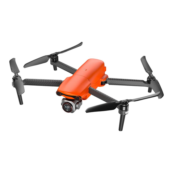
40 minutes. Also, it utilizes a three-axis stabilized gimbal, allowing you to view observed videos and data in real time through the Autel Sky Application. The EVO Lite Series aircraft adopts a foldable design and can hold its propellers for easy storage and transportation. -
Page 13: Product Acceptance Checklist
Chapter 1 Product Overview Product Acceptance Checklist The EVO Lite Series are available in three colors and come in standard and premium bundles. The packing list varies accordingly. After unboxing the product, please check whether the actual items match the items described in the following packing list and carefully inspect the appearance of the aircraft and all accessories. -
Page 14: Premium Bundle
Chapter 1 Product Overview Premium bundle Table 1-2 Packing List Item Model/Specification Quantity Note Includes 1 battery, EVO Lite Series propellers, 1 gimbal MDXM or MDXM2 Aircraft camera, and a gimbal protective cover. Spare Smart MDXM_6175_1113 Battery Battery Charger Multi Charger... - Page 15 Diameter of a propeller: 216 mm Type of the propeller: Folding propeller All the above components have passed Autel Robotics safety and compatibility tests, users can purchase and use accordingly. In case of adding any payload before flight, please evaluate the mounting weight reasonably.
- Page 16 Table 1-4 RC Components List Item Product Info Manufacturer Note Max. weight: 407 g Includes 2 EAN: 6924991102373 Autel Robotics command sticks UPC: 889520012119 and an antenna. Table 1-5 Firmware and Software version explanation Item Release Version Note Release Date...
-
Page 17: Flight Safety
The EVO Lite Series aircraft is a light unmanned aircraft, and the operation of this product by individuals under the age of 16 is prohibited by Autel Robotics. Users under the age of 16 must use this aircraft under the supervision of a professional adult. -
Page 18: The U.s
This product is not a toy, and individuals under the age of 16 are prohibited from operating In the EU region, The EVO Lite Series aircraft bears a C1 class identification label, and thus you must comply with subcategory A1 operational restrictions while using it, which are as follows: 1. -
Page 19: Other Countries And Regions
EASA Class 1 drones: (https://www.easa.europa.eu/document-library/general-publications/drones-information- notices) According to EU regulations, the EVO Lite Series aircraft is equipped with sensors (gimbal camera) capable of detecting personal data. Users are required to undergo legal registration when using the product. -
Page 20: Flight Environment Requirements
Chapter 2 Flight Safety Ensure a clear understanding of the type of flight activity (e.g., recreational, official, or business). Obtain permits from relevant authorities before flying. If necessary, consult with local legal professionals for detailed definitions and explanations of flight activity types. ... -
Page 21: Declaration Of Maximum Take-Off Mass
Chapter 2 Flight Safety stations, and TV broadcast signal towers. If significant interference occurs in these places during flight operations, the aircraft may not be able to fly normally, so return and landing should be done promptly. Choose open and spacious areas or high grounds for flying. Tall mountains, rocks, urban structures, and forests may obstruct the GNSS signal and the aircraft's video transmission signal. -
Page 22: Visual Positioning Function
Chapter 2 Flight Safety Aircraft Visual Perception Range When using the aircraft for flight, avoid obstructing the lenses of the visual perception system. Doing so may impact the performance of the aircraft's visual obstacle avoidance and could lead to flight accidents. ... -
Page 23: Visual Obstacle Avoidance Function
Chapter 2 Flight Safety If you lack extensive flight experience, try to avoid flying beyond visual range. When relying on visual localization for flight, avoid flying near surfaces such as water or snowy areas with mirror-like reflections. In poor GNSS signal conditions, ensure the aircraft is flying in well-lit environments with clear object surface textures. -
Page 24: Auto Return Home
Chapter 2 Flight Safety Extremely dark surfaces (light intensity less than 15 lux) or extremely bright surfaces. Small obstacles (such as wires, power lines, branches, etc.). Dirty lenses (such as water droplets, fingerprints, etc.). Scenes with low visibility (such as heavy fog, heavy snow, etc.). ... -
Page 25: Manual Activation Of Auto Return Home
Chapter 2 Flight Safety Manual activation of auto return home During flight, users can manually activate the auto return home by long-pressing the return-to- home button " " on the RC for 2 seconds or long-pressing and slide the return icon " "... -
Page 26: Behavior Activation Of Auto Return Home
Chapter 2 Flight Safety Behavior activation of auto return home During the flight, if "Signal Lost" is set to "Return to Home", when the RC disconnects from the aircraft for 4s, the Autel Sky will display a warning prompt “Aircraft disconnected” and the aircraft will activate auto-return. -
Page 27: Landing Protection Function
Chapter 2 Flight Safety During the flight, when triggering the automatic return due to loss of connection, low battery, or manually activating the automatic return, if obstacles are detected in front of the aircraft, the aircraft will automatically come to a stop, and it will ascend automatically to avoid the obstacles until it can resume normal flight over them. -
Page 28: Rebuilding Of The C2 Link
If decoding errors persist for a certain duration, leading to communication failure, the C2 link will be disconnected, and the aircraft will enter a reconnecting state. The loss of connection behavior for the EVO Lite Series aircraft includes two modes: “Go home”, “Resume”. -
Page 29: Restricted Zones
The EVO Lite Series aircraft is equipped with a built-in geofence system in the flight control system. Before each flight, ensure that the RC can connect to the internet to automatically update airspace restriction information, which will be synchronized to the drone. - Page 30 Chapter 2 Flight Safety the legal requirements of the current country or region. For more details, please refer to “2.10 Altitude and Distance Limits" in this chapter and “6.4 Settings Interface” in Chapter 6. Factory-installed in the geofence system, regularly updated. Factory-installed in the geofence system, regularly updated.
-
Page 31: Import Ugz
Chapter 2 Flight Safety When the aircraft not lifted flies towards the no-fly zone from the outside: When the aircraft touches the boundary of the buffer zone, Buffer zone of the no-fly the Autel Sky will display a warning alert "Approaching a Flight zone Restricted Area"... -
Page 32: Unlocking No-Fly Zones
5. Aircraft S/N (Serial number): Multiple serial numbers can be applied at once. 6. Autel account of UAS operator: Multiple accounts can be applied at once. Log in to the official website of Autel Robotics at www.autelrobotics.com/service/noflight/, enter the relevant information, and complete the waiver application. -
Page 33: Aircraft Calibration
Chapter 2 Flight Safety Altitude and Distance Limitation Diagram In the Autel Sky, the allowable range for altitude restriction is 25 ~ 800 m, and the allowable range for distance restriction is 30 ~ ∞ m. During actual flight, the set maximum altitude limit should not exceed the altitude restricted by local laws and regulations, such as the maximum flight altitude of aircraft in China’s Mainland, the United States, the European Union and other countries and regions should not exceed 120 meters or 400 feet. - Page 34 Chapter 2 Flight Safety Please stay away from strong magnetic field areas or large pieces of metal during calibration, such as magnetic ore, parking lots, construction areas with underground steel bars, near underground or overhead power transmission lines, etc. ...
-
Page 35: Imu Calibration
Chapter 2 Flight Safety Please follow the calibration steps as instructed on the Compass Calibration page of the Autel Sky. If the calibration fails, the rear arm light of the aircraft will turn solid red. In this case, repeat the above steps. - Page 36 Chapter 2 Flight Safety Flip the aircraft 180°, placing it with the belly facing up on a flat surface, until the rear arm light of the aircraft turns green and is always on. Please be careful to protect the lens on the back of the aircraft during this process.
-
Page 37: Gimbal Auto Calibration
If the propellers are stopped when the aircraft has a certain initial velocity, the aircraft will follow a parabolic trajectory during free fall. Do not stop the propellers in this unpredictable scenario. After completing the forced landing, please contact Autel Robotics promptly for inspection of the power system. -
Page 38: Direct Remote Identification
The EVO Lite Series aircraft supports the DRI system and uses Wi-Fi (Wi-Fi Beacon, 802.11n) for broadcasting. Enable the DRI system by configuring it in the Autel Sky. -
Page 39: Basic Flight Procedure
Chapter 2 Flight Safety Ensure the aircraft powers on and is connected to the RC, and the aircraft motors and gimbal camera are functioning properly. Confirm that the aircraft, RC, etc., have been upgraded to the latest versions as prompted. ... -
Page 40: Aircraft
Aircraft Aircraft Activation When unboxing the product for the first time, you need to activate the EVO Lite Series aircraft before using it. By default, the aircraft is pre-paired with the RC at the factory. After turning on the aircraft and the RC, you will see an activation prompt in the Autel Sky. Please follow the steps in the Autel Sky to activate the aircraft. - Page 41 Chapter 3 Aircraft Forward Visual Used to sense the obstacles ahead and avoid the aircraft from Perception System colliding with them. Integrates multiple sensors stable shooting Gimbal Camera measurements during flight. Front Arm Light Used to identify the nose direction of the aircraft. Motor Used to drive the propeller to rotate.
- Page 42 Chapter 3 Aircraft Used to connect to a computer for firmware updating, USB-C Interface debugging and data transferring. The USB-C interface of the aircraft is not available for charging. Please do not connect a charger to it. For aircraft charging, refer to “5.3.4 Charging the smart battery”...
-
Page 43: Propeller
Chapter 3 Aircraft Propeller Propellers are consumable parts that require regular maintenance and replacement to ensure the safe flight of the aircraft. The EVO Lite Series aircraft uses a quick-release propeller design, making it easy for you to replace them. Replacing propellers The propellers are installed in the aircraft by default at the factory, and reinstallation is not required. -
Page 44: Storing Propellers
Before each flight, make sure that all propellers are mounted correctly and securely. Please use the propellers provided by Autel Robotics. Do not mix propellers of different models. -
Page 45: Arm Light
Chapter 3 Aircraft Store the Propellers Before folding the arms, you should turn off the power of the aircraft. Store the propeller and fold the rear arms first, then fold the front arms. Arm Light After takeoff, the four arms of the aircraft each have an LED indicator at the end. The front arm light will periodically flash to assist users in identifying the front direction of the aircraft. - Page 46 Chapter 3 Aircraft (1s on/1s off) to distinguish the light on for 1s) to distinguish the nose direction of the aircraft. tail direction of the aircraft Table 3-7 Rear Arm Light Status Details Indicator status Definition (R: red G: green Y: yellow) Normal RYG–Alternating Flashing System Self-Test...
-
Page 47: Auxiliary Bottom Light
Chapter 3 Aircraft Auxiliary Bottom Light The aircraft is equipped with an auxiliary bottom light (LED auxiliary light) at the bottom of the fuselage. The lights are used to assist the downward Visual Perception System when the aircraft is landing in weak light environments, so as to ensure better visual positioning performance and enhance the landing safety of the aircraft. -
Page 48: Gimbal
Chapter 3 Aircraft RC Customizable Button: After setting the Fn button to "Photo/video switch”, you can switch the camera's mode by single-clicking or double-clicking this button. RC Customizable Button: After setting the Fn button to "AE Lock/Unlock”, you can control the camera's auto exposure by single-clicking or double-clicking this button. - Page 49 Chapter 3 Aircraft Used to control the moving range of the gimbal to rotate up or Pitch Axis Motor down (mechanical range: -135°~45°, controllable movement range: -90°~30°). Used to control the moving range of the gimbal to rotate left or Yaw Axis Motor right with its own axis (mechanical range: -45°~45°).
-
Page 50: Gimbal Mechanical Rotation Range
The mechanical rotation ranges of the pitch, yaw, and roll axes of the gimbal are shown below. Mechanical Rotation Range of the Gimbal of the EVO Lite Series aircraft Users can control the pitch rotation range of the gimbal: -90° to 30°. -
Page 51: Flight Control System
Do not disassemble the gimbal at will. Otherwise, warranty eligibility will be lost. Flight Control System EVO Lite Series aircraft achieves stable and convenient flight control through its built-in intelligent flight control system. The system supports a number of advanced functions, including auto-return, failsafe, and visual positioning system. -
Page 52: Flight Status
Chapter 3 Aircraft Ultrasonic sensor Measures the distance between the aircraft and the ground. Flight status Depending on the availability of GNSS signals and flight conditions, the aircraft can automatically switch between three flight modes. Table 3-12 Flight Status Mode Description GNSS mode is activated when the aircraft detects an appropriate GNSS signal. -
Page 53: Flight Modes
Chapter 3 Aircraft Flight modes The aircraft has varying flight performance in different flight modes. You can set the flight mode of the aircraft in the Autel Sky. For more information, please refer to “6.3 Status Bar” and “6.4 Settings Interface”... -
Page 54: Installing The Microsd Card
Chapter 3 Aircraft the take-off point in real time so as to make sure that the aircraft successfully lands at the take- off point. Landing Protection The landing protection function uses the downward Visual Perception System of the aircraft to create a depth image, and then calculates the flatness and angle of the depth image to detect whether the surface is flat enough for a safe landing. -
Page 55: Noise
30 minutes. Noise When the EVO Lite Series aircraft hovers, it generates noise with an intensity of 69dB (at a distance of 0.5 meters from the aircraft). Users should familiarize themselves with local noise pollution prevention and control regulations and set a reasonable flight altitude or safety distance to ensure no interference with other individuals, groups, or organizations. -
Page 56: Autel Skylink Image Transmission Function
Autel SkyLink Image Transmission Function The EVO Lite Series Aircraft is equipped with Autel SkyLink transmission technology, equipped with triple-frequency dual-transmit dual-receive capability, so that the communication distance between the aircraft and the RC can reach up to 10km. - Page 57 GNSS signal before proceeding to the actual operational area for the flight. Table 3-15 Global Certified Frequency Bands for EVO Lite Series aircraft (Image Transmission) Operating...
- Page 58 UK Australia Korea The EVO Lite Series Aircraft supports Wi-Fi fast transfer, and photos and videos on the aircraft can be downloaded to mobile devices at a transfer speed of up to 20MB/s through the Autel Sky.
- Page 59 Supplementary Information Standard configuration The RC is included as a standard item in the aircraft package, and Autel Robotics also provides retail packaging for customers to choose independently. Ensure that the control software version meets the above requirements when remotely...
-
Page 60: Remote Controller
Remote Controller Introduction The RC adopts the Autel SkyLink image transmission technology of Autel Robotics, has strong anti-interference capability and supports the double-emission and double-receiving of 2.4GHz, 5.8GHz and 5.2GHz. It can complete the control and setting of aircraft and camera within at most 12km distance and can display a high-definition picture in mobile device in a real-time manner by Autel Sky. - Page 61 Chapter 4 Remote Controller Transmits the control signals of the RC and receives the image Antenna transmission information of the aircraft. Mobile Device Used to mount a mobile device installed with Autel Sky. Holder Left command stick and right command stick control the direction and motion of aircraft.
-
Page 62: Communication Frequency Bands
Chapter 4 Remote Controller Shooting/Video After setting of the camera mode, press the button to take Recording Button photos or record videos. RC Customizable Use the Autel Sky to customize the button function. For more Button (Fn) information, please refer to “6.4 Settings Interface”... -
Page 63: Charging The Remote Controller
USB-A to USB-C cable and connect the plug of the charger to an AC power supply (100-240 V~ 50/60 Hz). Use the Charger to Charge the RC Please use the official charger provided by Autel Robotics to charge the RC. Using third- party chargers may damage the battery of the RC. -
Page 64: Preparing The Remote Controller
Chapter 4 Remote Controller After charging is complete, please disconnect the RC from the charging device promptly. It is recommended to fully charge the RC battery before the aircraft takes off. Generally, it takes about 120 minutes to fully charge the aircraft battery, but the charging time is related to the remaining battery level. -
Page 65: Connecting To Mobile Device
Chapter 4 Remote Controller When the RC is on, press and hold the power button on the RC until the controller emits a "beep" to turn off the RC. Be sure to turn off the aircraft before turning off the RC. Connecting to Mobile Device When the RC is on, extend the mobile device holder and mount the device (pre-installed Autel Sky App) in the holder. -
Page 66: Setting Stick Mode
Chapter 4 Remote Controller When you operate the aircraft, make sure that the aircraft is in the place for the best communications. Do not use other communication devices of the same frequency band at the same time to prevent interference with the signals of the RC. - Page 67 Chapter 4 Remote Controller Heading of the aircraft Right movement (Turn right) Stick Mode Types Table 4-5 Stick Modes Details Mode Stick Move Up/Down Move Left/Right Controls the forward and Controls the heading of Left Command Stick backward movement of the aircraft the aircraft Mode 1...
- Page 68 Chapter 4 Remote Controller Left Command The up-and-down direction of the left stick Stick is the throttle stick, which is used to control Move Up or the vertical lift of the aircraft. Down Push the stick up, and the aircraft will rise vertically;...
-
Page 69: Frequency Pairing With The Remote Controller
Chapter 4 Remote Controller Push the stick to the left, and the aircraft will tilt to the left and fly to the left of the nose; pull the stick to the right, and the aircraft will tilt to the right and fly to the right of the nose. -
Page 70: Using Combination Buttons (For Forced Frequency Pairing)
Chapter 4 Remote Controller When pairing, please keep the RC and the aircraft close together, at most 2 meters apart. If the mobile device is disconnected from the RC in the case of pairing, please reconnect them within 60s. Using combination buttons (for forced frequency pairing) Forced frequency pairing process is as follows: 1. -
Page 71: Remote Controller Keys
Chapter 4 Remote Controller When the aircraft is taking off or landing, keep it away from people, vehicles, and other moving objects. The aircraft will initiate a forced landing in case of sensor anomalies or critically low battery levels. -
Page 72: Return-To-Home Button And Pause Button
Chapter 4 Remote Controller After setting of the camera mode to Photo-taking, press the button to take photos. After setting of the camera mode to Video Recording, press the button to record videos, and press the button again to stop recording. -
Page 73: Calibrating The Remote Controller
Chapter 4 Remote Controller Return-to-Home Button and Pause Button When the aircraft pauses an auto-return, it will hover in place. To resume the auto-return, press the pause button “ ” again until the RC emits a "beep" sound. If the auto-return home point is not suitable for the aircraft to land (such as uneven ground and crowds), please exit the auto-return before the aircraft reaches the home point, and then manually resume control to land. - Page 74 Chapter 4 Remote Controller According to the calibration guide page of the RC, move the dial wheel and the left and right sticks according to the directions shown in the figure and hold for 1 second. At this time, the calibration direction icon will be changed to blue, indicating that the orientation calibration...
-
Page 75: Smart Battery
Smart Battery Battery Introduction The EVO Lite Series aircraft comes standard with the MDXM_6175_1113 smart battery (hereafter referred to as smart battery) as the power battery. This battery is a rechargeable lithium-ion polymer (LiPo) battery and features high energy density and capacity. The smart battery can be charged with an MaxAd_3SA battery charger. -
Page 76: Smart Battery Functions
Chapter 5 Smart Battery Smart Battery Functions The smart battery has the following functions: Battery Level Display The smart battery has a built-in battery level indicator, which shows the current battery level of the smart battery. Communication The aircraft can obtain real-time battery information, such as voltage, current, battery level, and battery temperature, through the communication interface on the smart battery. -
Page 77: Smart Battery Usage
Chapter 5 Smart Battery Once a short circuit is detected, the power supply of the smart battery will be cut off to protect the battery. Before using the smart battery, please carefully read and strictly follow the requirements in this Manual, “Battery Safety Operation Guidelines”, and “Disclaimer”, and those on the battery's surface sticker. -
Page 78: Installing/Removing The Smart Battery
Chapter 5 Smart Battery Installing/Removing the smart battery Table 5-2 Install the Smart Battery Step Operation Diagram Turn off the smart battery before installing the battery. Slowly insert the smart battery into the battery compartment on the aircraft fuselage, and you will hear a clicking sound when the battery is in place. -
Page 79: Turning On/Off The Smart Battery
Chapter 5 Smart Battery The unlock button of the smart batteries are consumable parts. Please do not press them hard to avoid any possible damage to the internal structure of the battery. Turning on/off the smart battery Turning on the smart battery When the smart battery is turned off, press and hold the power button for 3 seconds to turn on the battery. -
Page 80: Charging The Smart Battery
Chapter 5 Smart Battery Distribution of Battery Level Indicator Table 5-4 Battery Level Indicator Status (While Not Charging) : Green light is always on : Green light blinking : Off After the aircraft is connected to the RC, you can check the current smart battery level of the aircraft in the top status bar of the Autel Sky. - Page 81 Modifying the official smart battery or charging device provided by Autel Robotics is prohibited. Only use the battery and charging device provided by Autel Robotics. Autel Robotics is not responsible for any consequences, such as battery accidents and flight failure, caused by the use of third-party batteries or charging devices.
-
Page 82: Storing And Transporting The Smart Battery
Chapter 5 Smart Battery It is recommended to fully charge the smart battery of the aircraft before the aircraft takes off. When the battery is fully charged, the battery level Indicator will turn off. Generally, it takes about 90 minutes to fully charge the smart battery of the aircraft, but the charging time is related to the remaining battery level. -
Page 83: Maintaining And Handling The Smart Battery
Chapter 5 Smart Battery Do not store or transport the smart battery with sharp objects, watches, metal necklaces, earrings, or other metal items. Do not transport batteries that have a damaged appearance or a battery level of more than 30%. -
Page 84: Recycling The Smart Battery
Chapter 5 Smart Battery After the number of cycles of the smart battery reaches 200, it is recommended to replace the battery with a new one. After 2 consecutive standard charge and discharge operations, if the abnormal battery still cannot be repaired, it is recommended to replace it with a new one. -
Page 85: Autel Sky App
Autel Sky App Software Introduction The Autel Sky is a flight control software developed by Autel Robotics for aerial photography. The software integrates variety of professional functions, to make it easy to get started quickly, improve efficiency, and easily carry out aerial photography operations with the aircraft. -
Page 86: Status Bar
Chapter 6 Autel Sky App This feature page provides management of aerial photos and Album videos, as well as creative theme templates for users to facilitate post-production. Tap to enter the aircraft camera page (flight page), where you Start can view the aircraft’s flight attitude and aerial images in real time, and access the aircraft settings. -
Page 87: Settings Interface
Chapter 6 Autel Sky App Shows the current vehicle power situation and the Aircraft power estimated flight time. Displays the active status of the aircraft obstacle avoidance system. Obstacle Green indicates that the obstacle avoidance Avoidance system system is enabled. ... - Page 88 Chapter 6 Autel Sky App of 25-800m. Set the home point of the aircraft to "Me ", "Aircraft" or "Customize". Set the behavior of the aircraft when disconnected to "Return to Home", "Hover" or "Descend". Perform compass calibration and IMU calibration for the aircraft.
-
Page 89: Map Interface
Chapter 6 Autel Sky App Delayed original image: Can be set to "JPG", "RAW" or "Do not retain the original image". Panoramic original image: Can be set to "JPG" or "RAW". Portrait/Follow/ Night Scene: Default is "JPG". ... - Page 90 Chapter 6 Autel Sky App After the function interface is switched, the selected interface will be displayed in full screen on the mobile device, while the other page will be shown in a small window at the bottom left of the screen. Map Interface Table 6-4 Details of the Map Interface Name...
-
Page 91: Camera Interface
Chapter 6 Autel Sky App You can locate the RC, home point, and the position of the Location aircraft on the map. Locate My Drone Used to find the aircraft lost in abnormal flying Camera Interface Users can freely switch between shooting and video functions on the camera interface to realize night scene, panorama, hyperlapse, shooting, portrait, quick shot, tracking and other camera functions. - Page 92 Chapter 6 Autel Sky App Scene property After switching the shooting scene for the gimbal camera, tap settings the icon to perform related function settings. Tap to display detailed properties of the lens on the right Camera properties sidebar. When selecting the recording working mode, tap the recording button to start recording; tap the recording button again to end recording.
- Page 93 Chapter 6 Autel Sky App After a quick short is shot, users can view the captured footage in the album and select to download it to a mobile device. Users can also click the one-click video icon in the bottom right corner to automatically generate a short film.
-
Page 94: Firmware Updates And Maintenance
Chapter 7 Firmware Updates and Maintenance Firmware Updates and Maintenance In order to optimize aircraft performance, Autel Robotics will update relevant firmware when necessary. Users can upgrade the firmware of the aircraft, the RC, and the smart battery online through the Autel Sky. -
Page 95: Troubleshooting Guide
Users can contact Autel Robotics to purchase the above parts and replace them by themselves according to the operating instructions. If you need to replace parts that are not in the list, please contact Autel Robotics. Damage caused by unauthorized disassembly and assembly will not be covered by the warranty. - Page 96 Chapter 7 Firmware Updates and Maintenance 1. If the aircraft displays a fault during self-check (the tail LED indicator will turn solid red): For hardware problems, please contact Autel Robotics customer support. 2. If the motor fails to start, please check the following issues: ...
- Page 97 If it can power on normally, make sure that the device is sufficiently charged before proceeding with the update; If the device cannot power on, contact Autel Robotics. 16. For the purpose of device safety, please do not use unknown USB device or other external...
-
Page 98: Appendix A Product Specifications
Appendix A Product Specifications Appendix A Product Specifications A.1 Aircraft Aircraft Weight of EVO Lite Series Aircraft 835 g (With propellers, battery) Maximum takeoff weight 866 g Folded: 210×123×95mm Dimensions Unfolded: 433×516×95mm Max. rotation speed 8000 rpm Wheelbase 368 mm... - Page 99 Appendix A Product Specifications Standard: 30° Ludicrous: 33° Smooth: 60°/s Maximum rotation angular speed Standard: 120°/s Ludicrous: 200°/s Working temperature 0~40℃ Battery hot replacement not support Internal storage Onboard storage: 6GB 2.4G: 2.400 – 2.4835 GHz* 5.1G: 5.15 - 5.25 GHz** 5.8G: 5.725 - 5.829 GHz***, 5.725 - 5.850GHz *Only applies to MIC regions Wi-Fi Operating Frequency...
- Page 100 Appendix A Product Specifications *Only applies to SRRC regions **Only applies to FCC regions ***Only applies to MIC regions Note: Some frequencies are only available in some regions and some frequencies are only allowed for indoor use. Check local laws and regulations for details. Maximum signal effective distance FCC: 10 kilometers (No interference, no obstruction)
-
Page 101: A.2 Gimbal Camera
Appendix A Product Specifications A.2 Gimbal Camera A.2.1 Camera - Lite Zoom camera Image sensor 1/1.28’’ CMOS, 50 million pixels Field of view: 85° 35 mm format equivalent focal length: 23 mm Lens Aperture: f/1.9 Focus distance: 0.5 meter ~ ∞ Focus: PDAF + CDAF Video: ISO100 ~ ISO6400 ISO range... -
Page 102: Camera - Lite
Appendix A Product Specifications 1920×1080 P60/P50/P48/P30/P25/P24 Video format MP4 / MOV (8-Bit) Video coding format H.265/H.264 Video maximum bit rate 120Mbps Original image: 3840×2160, JPG/DNG Timelapse Video: 4K P25 Horizontal/Vertical/Wide-angle/Spherical Panorama Original image: 4096×3072, JPG/DNG Support file system FAT32/exFAT Gimbal Pitch: -135°~45°... - Page 103 Appendix A Product Specifications Others: 1/8000 ~ 1 seconds Real-time image transmission portrait blur and photo Portrait blur portrait blur Defog mode Support 1 - 16x digital zoom Zoom Lossless zoom: 4K: 1.3 times; 1080p: 3 times 5472×3648 (3:2) Maximum photo size 5472×3076 (16:9) 3840×2160 (16:9) Photo format...
-
Page 104: A.3 Remote Controller
Appendix A Product Specifications Stable system Three-axis stabilization Maximum control speed (pitch) 30°/s Angualr vibration range ±0.003° A.3 Remote Controller Material PC+ABS Operating Temperature 0℃ to 40℃ Battery capacity 3930mAh ~ 2.5h (when connected to a mobile phone) Battery Life ~ 3.5h (when not connected to mobile phone) Interface type USB-C... -
Page 105: A.4 Smart Battery
Appendix A Product Specifications Realtime transmission Transmission distance<1km: 2.7K 30fps quality Transmission distance>1km Transmission bitrate 90Mbps Transmission delay ≤ 200 ms A.4 Smart battery Smart Battery MDXM_6175_1113 Operating Temperature 0~+40℃ Battery Type LiPo 3S Rated Capacity 6175 mAh Battery energy 68.7 Wh Voltage 11.13 V... - Page 106 Appendix A Product Specifications Rated power 63.75W Max...
-
Page 107: Appendix B Declaration Of Conformity
Appendix A Product Specifications Appendix B Declaration of Conformity... -
Page 108: Appendix C Drone Pilot Information Notices
Appendix B Declaration of Conformity Appendix C Drone Pilot Information Notices When flying this aircraft product in the territory of EU Member States, please comply with the following EASA regulations. - Page 109 Appendix C Drone Pilot Information Notice You can visit the EASA official website to get other language versions: https://www.easa.europa.eu/en/document-library/general-publications/drones-information- notices.
Need help?
Do you have a question about the EVO Lite Series and is the answer not in the manual?
Questions and answers