Table of Contents
Advertisement
Quick Links
Advertisement
Table of Contents

Related Manuals for Autel Robotics EVOII RTK Series


Summary of Contents for Autel Robotics EVOII RTK Series
- Page 1 Series EVO II RTK User Manual...
- Page 2 Manual are the registered trademark of their respective owners. Copyright Without the explicit consent of Autel Robotics, do not copy or forward any part of the Manual in or by any form (electronic, mechanical, reproducing, recording or other forms). Patent Information This product was obtained according to patent procedures.
- Page 3 Autel Robotics data server. All remote sensing data and flight logs are stored in the data server in the United States, but the data can be uploaded automatically only when the flight log backup option is enabled.
- Page 4 When the aircraft battery is installed or removed, be sure to turn off the aircraft power. Other precautions are as follows: It is only allowed to use the battery and charger sold or authorized by Autel Robotics for EVO II RTK series. The use of any unapproved battery or charger may cause fire, explosion, leakage or other dangers.
- Page 5 All warnings and errors displayed on App have been handled. Only accessories provided with this aircraft or sold or authorized by Autel Robotics can be used with this aircraft. Using unapproved accessories can bring serious safety risks and will invalidate the product warranty.
- Page 6 Warning If any part of the aircraft or the remote controller fails to work normally or is visibly damaged, please do not fly any longer and contact the Autel Robotics customer service team: www.autelrobotics.com/page/contact Storage and maintenance Carefully check each part of the aircraft after any collision or extrusion. Store the aircraft and its accessories out of the reach of children and pets.
-
Page 7: Table Of Contents
Catalog Chapter 1 About the Manua........................ 9 1.1 Instructions for the first flight....................... 9 1.1.1 Documents of start guide....................9 1.1.2 Autel Explorer App installation..................9 Chapter 2 Be familiar with your smart UAV..................10 2.1 Aircraft............................10 2.1.1 Function description......................10 2.1.2 Flight indicator......................... - Page 8 Chapter 6 Annex..........................60 6.1 Authentication information and restricted area................60 6.1.1 Authentication information....................60 6.1.2 Diagram of restricted area....................61 6.2 Specifications..........................63...
-
Page 9: Chapter 1 About The Manua
1. Product List: a list of all items that shall be included in the packing box. For any missing, please contact the Autel Robotics customer support or your local retailer. 2. User Manual: to instruct you to well learn operating methods of EVO Ⅱ RTK series products. -
Page 10: Chapter 2 Be Familiar With Your Smart Uav
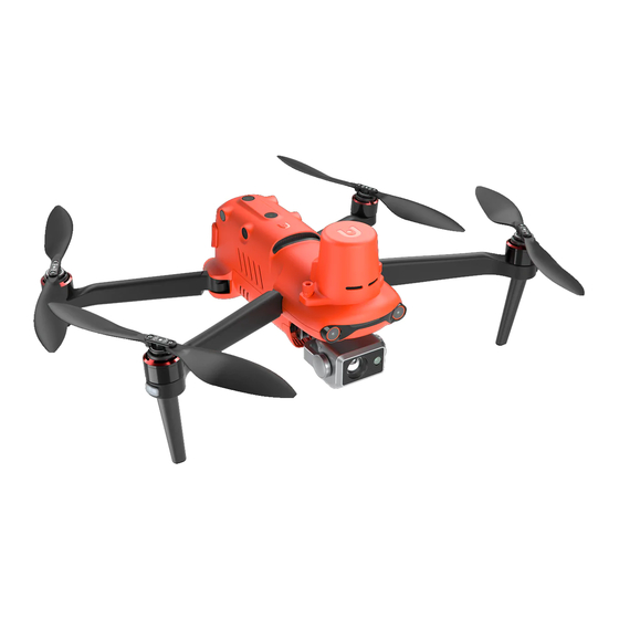
Chapter 2 Be familiar with your smart UAV. Start your journey of exploration, discovery and creation from now on. EVO II RTK series UAVs integrate a novel RTK module to provide real-time centimeter-level positioning data and support PPK post-processing. The aircraft can record satellite raw observation data, camera exposure parameters and other data. - Page 11 ① Propeller ⑤ Gimbal camera ② Motor ⑥ Undercarriage ③ RTK module ⑦ Front LED indicator ④ Forward vision system ⑧ Power button ⑩ Rear LED indicator ⑨ Backward vision system ⑪ Left vision system ⑫ SD card slot ⑬Right vision system ⑯...
- Page 12 ⑱ Upper visual system ㉑ Lower visual system ⑲ Ultrasonic sensor ⑳ LED fill-in light Remark: The right side is equipped with a protective cover, for protecting the USB-C port and Remote controller pairing button/pairing indicator. Ensure that the protective cover is kept in the closed state during flight.
-
Page 13: Flight Indicator
Flight indicator 2.1.2 The aircraft has one LED indicator at the end of each arm. The front LED shows steady red to help you to find the head direction. The rear LED shows the current flight status of aircraft. The following table shows the meaning of each status indicator. - Page 14 of high energy density and large capacity, and shall be charged with the provided special charger. Basic functions Aircraft battery ① Disconnect button ② Battery level indicator ③ Power button Turn on battery The battery shall be turned off before it is installed. After installation, long press the power button for 3s.
- Page 15 Additional functions The following functions can protect and prolong the battery service life. Self-discharge protection for storage If the battery is stored in high temperature environment or it is not used for 6 days and the battery level is high, the self-discharge protection will be activated. The battery will automatically discharge to a safe level, this is a default setting, and this discharging process takes 2-3 days.
-
Page 16: Gimbal And Camera
LED warning description LED 1 LED 2 LED 3 LED 4 Warning description The charging temperature is too high or too low. The charging current is high enough to cause short circuit. There is overcurrent, overload or short circuit problem in the case of discharging. - Page 17 ① MCU installation disc ⑤ Pitching axis motor ② Shock absorber ⑥ Rolling axis motor ③ Camera ⑦ Yawing axis motor ④ Filter Gimbal of EVO II Dual 640T RTK: Support infrared camera and 8K camera ① MCU installation disc ⑤...
- Page 18 The gimbal includes two working modes: Stabilization mode : The rolling axis remains horizontal while the pitching axis remains the user-defined angle. This mode is used to capture stable image and video. mode : The rolling axis remains consistent with the rolling direction of the aircraft ...
- Page 19 Gimbal installation 1. Pinch the tail of the shock absorber with your thumb and index finger. Slide the gimbal down and forward in a straight line along the gimbal compartment slot. 1) Please make sure that the ring at the front end of the gimbal is aligned with the two pins in the gimbal compartment of the machine head.
- Page 20 4. Turn on the power switch of the aircraft. If the connector cable of the gimbal is connected correctly, the gimbal will rotate automatically to carry out self inspection. Remark: Pick up the aircraft and turn it over so that the gimbal faces down. When installed correctly, the gimbal will be remained firmly in its current position.
-
Page 21: Built-In Intelligent Flight Control System
Warning To prevent file loss, turn on the aircraft before the Micro SD card is taken out. Transfer files to computer To transfer images and videos to the computer, please connect the computer to the aircraft via the USB-C port, as shown below. -
Page 22: Intelligent Flight Features
Flight Mode According to GPS availability and flight conditions, EVO Ⅱ RTK series can automatically switch between three flight modes. Flight Mode Description Flight Mode When the aircraft detects an appropriate GNSS signal, it will activate the GPS mode. With the assistance of the forward and downward vision GPS mode systems, GPS can locate and avoid obstacles, provide stable and smooth flight control, and support safety functions such as return, fail-safe, etc. - Page 23 The return altitude is 30 m (90 ft) by default. If you activate the return function when the aircraft is below this altitude, the aircraft will rise to 30 m (90 ft) before performing return. If the auto return function is activated within a radius of 10 m (30 ft) of the return point, the ...
-
Page 24: Omnidirectional Binocular Vision System
Landing features Landing protection When the aircraft arrives above the return point, the landing protection function will be activated to detect the ground environment. If the ground is flat, the aircraft will land automatically. Otherwise it will hover on the spot to wait for the next instruction. Precise landing ... - Page 25 Backward The tail of the aircraft 0.5 - 16 m (1.5 ft - 52 ft) Respectively at the rear parts of the left Left/Right 0.5 - 12 m (1.5 ft - 39ft) and right sides of the aircraft Upward The upper part of the aircraft 0.5 - 12 m (1.5 ft - 39ft) Downward The lower part of the aircraft...
- Page 26 Remark Omnidirectional obstacle sensing directions include front, back, up, down, left and right. However, there are blind spots in the four diagonal directions. In manual flight, attention should be paid to the surrounding environment and App prompts to guarantee safety. Do not operate the aircraft in a complex environment where there is insufficient light, small ...
-
Page 27: Rtk Module
ultrasonic device, such as ultrasonic range finder, fault detector, cleaner or welding machine. Function description Intelligent tracking Intelligent tracking uses deep learning algorithms to detect six types of objects in real time: pedestrians, cyclists, cars, trucks, boats and animals. Real-time tracking algorithms are used to automatically track selected objects while avoiding obstacles in flight. -
Page 28: Industry Application
2. Enter the camera interface of Autel Explorer App> select the setting button ( )> RTK at the upper right corner, and select the RTK service type as "Network RTK". Autel Robotics has given users a designated network RTK package, which does not need to be purchased during the validity period. - Page 29 the value. Flight speed: the flight speed when the aircraft flies to this waypoint. The aircraft will gradually adjust the flight speed to the set value during the flight to this waypoint. Click the waypoint> select "Flight Speed"> slide left and right to change the value. Action: Click the waypoint>...
- Page 30 Rectangular task Polygon task Oblique photography Flight altitude √ √ √ Oblique height √ √ √ Ground resolution ▲ ▲ ▲ (GSD) Oblique ground × × ▲ resolution Flight speed √ √ √ Oblique speed × × √ Forward overlap √...
-
Page 31: Remote Controller
aircraft will return automatically. Very low battery level: The aircraft will end the task and automatically land on the spot. Too weak GPS signal: The UAV enters the ATTI mode and switches to manual control. Historical task The user can name and save the flight tasks, which are displayed in the order of creation time. - Page 32 A viewing angle of 180º can be adjusted, to provide an ① Mobile device support optimal viewing effect. To display flight status, warning messages and real-time ② Flight information panel video images. ③ Rocker Control the direction and motion of aircraft. ④...
- Page 33 ⑮ Button B Use Autel Explorer App to set functions. ⑯ Video button To start or stop video recording. ⑰ Gimbal pitch angle thumbwheel To control the pitch angle of the camera gimbal 2.2.2 Real-time observation panel Flight information panel After the aircraft is connected, the following main interface will be displayed.
- Page 34 ⑧ Remote controller signal To display current signal intensity Estimated time that the aircraft can stay in the air based on ⑨ Remaining flight time the remaining power To indicate whether the image and video are stored in the ⑩ Storage mode memory carried by the aircraft self or Micro SD card ⑪...
- Page 35 Estimated time that the aircraft can fly in the air based on ① Remaining flight time the remaining power ② Remote controller battery To display current battery level To display the altitude of the aircraft relative to the return ③ Altitude point To display the horizontal distance between the aircraft and ④...
- Page 36 Video, single, continuous (3/5 frames), timed (2/5/7/10/20/30/60s), Camera mode AEB (3/5), pure night scene, HDR imaging, long exposure 8K (7680x4320), 6K (5760 x 3240), 4K (3840 x 2160), 2.7K (2720 Video resolution x 1528), 1080p (1920 x 1080) Video frame rate 120 fps, 60 fps, 50 fps, 48 fps, 30 fps, 25 fps, 24 fps Visible light mode: 8000 x 6000, 7680 x 4320, 4000 x 3000, 3840 x 2160...
- Page 37 Remote controller setting 1. Rocker mode Mode 1 (Japanese manipulator), mode 2 (American manipulator) and mode 3 (Chinese manipulator) enable you to control the aircraft based on your own preference, as shown below. Indicator Aircraft motion Raise Descend Turn the head left Turn the head right Forward Backward...
- Page 38 Remote controller alarming sound Make a short beep every second for 5s, and Alarm of low aircraft battery level the remote controller vibrates twice at the same (The default is 25%) time Make five short beeps every second for 5s, and Alarm of very low aircraft battery level the remote controller vibrates for five times at (The default is 15%)
-
Page 39: Chapter 3 Flight Preparation
Chapter 3 Flight preparation The EVO II RTK series is convenient and unique in design and is fully assembled before delivery. To ensure the safe operation of the UAV, please read the following instructions and warnings before the first flight. 3.1 Battery preparation 3.1.1 Install aircraft battery 1. - Page 40 Charge the aircraft and the remote controller 1. Insert the charge wire by the following steps: Aircraft battery: Insert the charge connector into the charge interface of the battery. Remote controller: Open the protective cover of USB port, and insert the charge wire provided. 2.
-
Page 41: Remote Controller Preparation
Battery level indicator status (Charging status) - Green is normally on - Green is flashing During charging: The remote controller power button ( ) turns green when the power switch is turned on, and turns red when the power switch is turned off. You can monitor the charging process through the flight information panel. -
Page 42: Turn On/Off Remote Controller
Remark As shown in the figure, the antenna can be turned for 270 degrees. Antenna position adjustment Keep the two antennas upright and parallel to each other, as shown in the figure below. Intensive Weak 3.2.2 Turn on/off remote controller ... -
Page 43: Remote Controller Calibration
Remark When the aircraft is not connected, if there is no operation for 15 minutes, the remote controller makes beep and will automatically turn off after 18 minutes. 3.2.3 Remote controller calibration If the rocker is abnormal (for example, the remote controller falls on the ground or the flight direction of the aircraft is not consistent with its operation direction), the remote controller is recommended to be calibrated. -
Page 44: Aircraft And Remote Controller Pairing
4. Push and hold the rocker in eight directions one by one until you hear a beep. Then turn the gimbal pitch angle knob clockwise until you hear a beep, and turn it counterclockwise until you hear a beep. 3.2.4 Aircraft and remote controller pairing The remote controller and the aircraft have been paired in factory. -
Page 45: Aircraft Preparation
3. Press the remote controller pairing button for 3s at the right lower part of the aircraft. The pairing indicator flashes rapidly, indicating that the aircraft is prepared to be paired with the remote controller. 4. Press and hold the power button ( ) and return button( ) for 2s at the same time until "Autel"shows on the flight information panel. - Page 46 Please first extend the front arm, and then the rear arm. Important Before turning off the remote control, always turn off the aircraft power switch. Before folding the arms, turn off the aircraft power switch. Fold the rear arm and propeller first, and then fold the front arm.
- Page 47 Propeller With white mark Without white mark Schematic diagram Installation Installed to the mount without white Installed to the mount with white mark position mark Locking direction: rotate the propeller to tighten it as shown in the figure. Legend Unlocking direction: rotate the propeller to remove it as shown in the figure. ...
- Page 48 Keep away from all electronic devices (such as mobile device) that may interfere with the calibration. Calibration procedure: 1. Press the takeoff/landing button ( ) and return button ( ) on the remote controller at the same time for 3s. When the calibration process starts, the LED indicator on the back of the aircraft turns yellow and flashes.
-
Page 49: Chapter 4
Chapter 4 Flight Operation 4.1 Check list before flight Perform comprehensive check before flight by the following steps: Fully charge the aircraft battery, remote controller and your mobile device. Take down the gimbal protective cover. Confirm that the propeller is intact and correctly installed. ... -
Page 50: Motor Start And Aircraft Takeoff
Basic flight 1. Place the aircraft at an open area. Stand at least 5 m (15 ft) from the tail of the aircraft. 2. Turn on the remote controller. 3. Turn on the aircraft, and wait the LED indicator at the tail to turn green and flash slowly. 4. -
Page 51: Manipulator Control (American Manipulator)
4.2.2 Manipulator control (American manipulator) Reminding If you are the first time to control the aircraft, please move the rocker gently till that you are familiar with its operation. Left rocker Raising/descend Push the rocker up and down, to control raising and descending of the aircraft. Left view Left view Down... - Page 52 Right rocker Forwards/backwards Push the rocker forwards and backwards, to control the aircraft to move forwards and backwards. Left view Left view Forward Backward Tail Tail Head Head Push down Push up Move leftwards/rightwards Push the rocker leftwards or rightwards, to control the aircraft to move leftwards or rightwards. Rear view Rear view Rightward...
- Page 53 Move leftwards/rightwards 1. Find an appropriate aircraft landing position. 2. When the aircraft arrive above the target position, release the rocker to make the aircraft hover. 3. Slowly push down the left rocker to land the aircraft. Turn off the motor ...
- Page 54 Passive landing When any of the following conditions are met, the fail-safe protection will be triggered and the aircraft will automatically land from its current position. The alarm of low battery level can be activated in a non-GPS environment. ...
-
Page 55: Chapter 5 Maintenance And Service
Maintenance and service 5.1 Firmware update In order to optimize the system performance of EVO II RTK series aircrafts, Autel Robotics will update relevant firmware when necessary.You can download a unified firmware upgrade package on the official website, which contains the latest versions of various firmware such as flight controller, gimbal, camera, smart battery and remote controller. -
Page 56: Solutions To Common Faults
5.2 Solutions to common faults Q1. The aircraft displays a fault during the self-inspection (the tail LED indicator is normally on red): Hardware problems are detected. Please contact the intelligent customer support of Autel Robotics here: www.autelrobotics.com/page/contact Q2. If the motor cannot be started, please check the following: Whether the remote controller and the aircraft are paired. -
Page 57: Storage And Maintenance
Please contact the customer support of Autel Robotics for any damage. Only use the accessories authorized by Autel Robotics, such as charger. We will provide no warranty for any accident due to the use of unapproved accessories. -
Page 58: Customer Service
Scope of service: Within the warranty period, the product has the non-human performance fault during normal use; The product is not disassembled without approval or modified or added as instructed by non-official manual, or has other non-human faults; The equipment serial number, factory label and other marks are not torn away or altered;... -
Page 59: Maintenance Service
North America/Europe Tel: (844) 692-8835 Email: support@autelrobotics.com support.eu@autelrobotics.com Website: www.autelrobotics.com 5.5.2 Maintenance service If you want to return your equipment for repair, please mail to support@autelrobotics.com or call the customer support of Autel Robotic: 0755-2690 8091. You are advisable to provide the following information: Name ... - Page 60 Chapter 6 Annex 6.1 Authentication information and restricted area 6.1.1 Authentication information FCC Warning Message Any Changes or modifications not expressly approved by the party responsible for compliance could void the user’s authority to operate the equipment. This device complies with part 15 of the FCC Rules. Operation is subject to the following two conditions: (1) This device may not cause harmful interference (2) this device must accept any interference received, including interference that...
- Page 61 following two conditions: (1) this device may not cause interference, (2) this device must accept any interference, including interference that may cause undesired operation of the device. Le présent appareil est conforme aux CNR d’Industrie Canada applicables aux appareils radio exempts de licence. L’exploitation est autorisée aux deux conditions suivantes: (1) l’appareil ne doit pas produire de brouillage, et (2) l’utilisateur de l’appareil doit accepter tout brouillage radioélectrique subi,...
- Page 62 aircraft is limited and such height limit varies with the radius. When the radius decreases from 8km to 2.4km, the maximum flight height will decrease from 120m to 10.5m. Warning area APP will give a warning information when the aircraft enters the area of 8.1km from the airport. Remark When the aircraft enters any take-off restricted area, it will land automatically.
- Page 63 6.2 Specifications Aircraft Weight (including propeller and 1250g±0.5g(EVO II Dual 640T RTK) battery) 1237g±0.5g(EVO II Pro RTK) Wheel base 397mm Max. flight time (wind-free 36 minutes environment) Max. horizontal flight speed 72 km/h (positioning mode) 5 m/s (automatic flight) Max. takeoff speed 8 m/s (manual manipulation) Max.
- Page 64 GNSS Single frequency high sensitivity GPS+BeiDou+Galileo (Asian regions) GNSS GPS+GLONASS+Galileo (other regions) Use frequency points: GPS: L1/L2; GLONASS: L1/L2; BeiDou: B1/B2; Galileo: E1/ E5 Multi-frequency multi-system First positioning time: < 50 s high-precision RTK GNSS Positioning accuracy: Vertical 1.5 cm + 1 ppm(RMS); Horizontal 1 cm + 1 ppm(RMS) 1 ppm means that the error is increased by 1 mm for every 1 km that the aircraft moves.
- Page 65 Zoom 1-16 times (max. 3 times lossless zoom) Single Continuous: 3/5 frames Automatic enclosure exposure (AEB): 3/5 enclosure frame (under 0.7EV offset) Timing: Picture taking mode JPG: 2s/5s/7s/10s/20s/30s/60s DNG: 5s/7s/10s/20s/30s/60s Pure night shooting: Support (in 4K JPEG format) Long exposure: max. 8s HDR imaging: (in 4K JPEG format) 5472*3648 (3:2) Photographic resolution...
- Page 66 Infrared mode: 640*512 Photographic resolution Picture-in-picture: 1920*1080, 1280*720 Picture format TIFF+JPG (with irg file) Video format MP4 / MOV (support H.264/H.265) Video resolution 640*512 30fps Temperature measuring ±3℃ or ±3% of reading (which ever is larger) precision @ ambient temperature -20℃-60℃ High gain mode: -20°...
- Page 67 8K 7680*4320 p25/p24 6K 5760*3240 p30/p25/p24 Video resolution 4K 3840*2160 p60/p50/p48/ p30/p25/p24 2.7K 2720*1528 p120/p60/p50/p48/p30/p25/p24 1080P 1920*1080 p120/p60/p50/p48/p30/p25/p24 Max. video bitrate 120Mbps Vision system Type of video system Omnidirectional binocular vision system Accurate measurement range: 0.5 - 20 m Detection range: 0.5 - 40 m Forward vision Effective sensing speed:<...
- Page 68 Remote controller and image transmission Max. desired signal distance 9km FCC, 5km CE ( (no interference, no blockage) Working frequency 2.4-2.4835GHz 2.4-2.4835GHz FCC: ≤26 dBm ISED: ≤26 dBm Transmission power CE: ≤20 dBm RCM: ≤20 dBm SRRC: ≤20 dBm Real-time image transmission 720p@30fps / 1080p@30fps quality Max.
- Page 69 Storage temperature & humidity -10-30℃, 65±20%RH Recommended storage 22-28℃ temperature Max. charging power 1.7A@3.7V consumption (W) Charging time 90 minutes Charger Input 100-240 V, 50/60 Hz, 1.5A 13.2 V ⎓ 5 A Output 5V⎓ 3A 9V⎓ 2A 12V⎓ 1.5A Voltage (V) 13.2±...
Need help?
Do you have a question about the EVOII RTK Series and is the answer not in the manual?
Questions and answers