Table of Contents
Advertisement
Quick Links
Advertisement
Table of Contents

Related Manuals for Force USA C10 SLIDING BENCH


Summary of Contents for Force USA C10 SLIDING BENCH
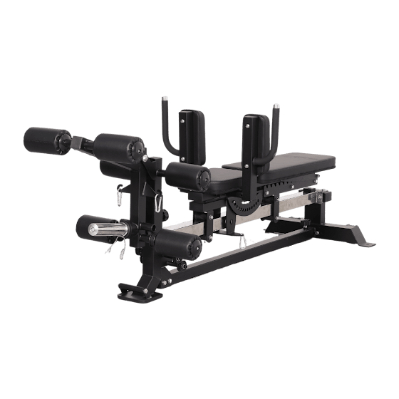
- Page 1 C10 SLIDING BENCH USER MANUAL | F-C10-SB...
-
Page 2: Table Of Contents
TABLE OF CONTENTS PAGES SECTION Before you Start and Safety Information ForceUSA App Preventative Maintenance 5-10 Parts Identification 11-26 Assembly Steps 30-42 Exploded Diagrams 43-45 Parts Lists Warranty Information F-C10-SB... -
Page 3: Before You Start And Safety Information
USER MANUAL Before You Start Read all instructions in this manual before assembling or using this equipment Remove all parts from the packaging and count each component separately to ensure everything is provided correctly, noting that some items may be pre-assembled Follow the instructions and refer to both the individual assembly pages and the exploded views of the equipment whenever possible The owner is responsible for ensuring that all users of this unit have read the user manual and... -
Page 4: Forceusa App
FORCE USA TRAINING APP The Force USA training app offers programs, tutorials, progress tracking and more. Not compatible with all Force USA equipment. DOWNLOAD F-C10-SB... -
Page 5: Preventative Maintenance
PREVENTATIVE MAINTENANCE To ensure your equipment is operating at its peak, please follow the below preventative maintenance schedule performing all tasks upon initial assembly: Daily Maintenance Wipe down the equipment to remove any dust and sweat residue with a dry, non-abrasive cloth Inspect the unit for noisy, damaged or loose components Monthly Maintenance... -
Page 6: Parts Identification
PARTS IDENTIFICATION Parts Shematic Diagram Key No. Description Quantity Front Base Frame Middle Base Frame Rear Base Frame Internal Support Beam Sliding Frame Locking Plate Back Pad Frame Seat Pad Frame Pad Adjustment Plate Back Pad F-C10-SB... - Page 7 PARTS IDENTIFICATION Parts Shematic Diagram Key No. Description Quantity Seat Pad Pulley Leg Curl Extension Inner Shaft Leg Curl Extension Mounting Frame Leg Curl Extension Frame Pulley Foam Pad Rod Upper Foam Pad Foam Pad Inner Cover Plate Foam Pad Outer Cover Plate F-C10-SB...
- Page 8 PARTS IDENTIFICATION Parts Shematic Diagram Key No. Description Quantity Lower Foam Pad Spring Collar Carabiner Leg Curl Cable Preacher Curl Frame Preacher Curl Barbell Holder Preacher Curl Pad Leg Press Hack Squat Cable - Green Leg Press Hack Squat Cable - Red Leg Press Hack Squat Plate Adjustment Frame F-C10-SB...
- Page 9 PARTS IDENTIFICATION Parts Shematic Diagram Key No. Description Quantity Inner Shaft Leg Press Hack Squat Plate Shoulder Pad Frame Shoulder Pad F-C10-SB...
- Page 10 PARTS IDENTIFICATION 26. M8X60 (x4) 28. M10X50 (12.9) (x4) 17.φ 12X118-M10 (x1) 20.φ 12X130-M10 (x1) 46.M8X20 (x4) 3.M10X75 (x2) 22.M8X16 (x2) 13.M10X85 (x2) 15.M10X105 (x2) 6.M10X25 (x8) 53.M8X65 (x4) 45.M10X70 (x2) 12.M10X90 (x2) F-C10-SB...
- Page 11 PARTS IDENTIFICATION 5. φ 10 (x35) 4. M10 (x15) 7. φ 10 (x12) 11. φ 30* φ10.5*T3 (x4) 23. φ 8 (x2) 21. φ 8 (x14) 1PCS 17-19 2PCS 5. 8MM 1PCS F-C10-SB...
-
Page 12: Assembly Steps
ASSEMBLY STEP 1 Description Note Quantity Key No. Front Base Frame Middle Base Frame Hexagon Head Bolt M10×75 Lock Nut Washer φ10 Hexagon Head Bolt M10×25 Spring Washer φ10 Rear Base Frame F-C10-SB... - Page 13 ASSEMBLY STEP 2 Description Note Quantity Key No. Internal Support Beam F-C10-SB...
- Page 14 ASSEMBLY STEP 3 Key No. Description Note Quantity Lock Nut φ10 Washer Hexagon Head Bolt M10×25 φ10 Spring Washer Sliding Frame Large Washer φ10 M10×90 Hexagon Head Bolt Hexagon Head Bolt M10×85 F-C10-SB...
- Page 15 ASSEMBLY STEP 4 Key No. Description Note Quantity Lock Nut Washer φ10 Locking Plate Hexagon Head Bolt M10×105 F-C10-SB...
- Page 16 ASSEMBLY STEP 5 Description Note Quantity Key No. Lock Nut Washer φ10 Back Pad Frame Double Head Bolt φ12*M10*118 Seat Pad Frame F-C10-SB...
- Page 17 ASSEMBLY STEP 6 Key No. Description Note Quantity Lock Nut Washer φ10 Pad Pad Adjustment Plate Double Head Bolt φ12×130-M10 Washer φ8 Hexagon Head Bolt M8×16 φ8 Washer F-C10-SB...
- Page 18 ASSEMBLY STEP 7 Key No. Description Note Quantity Washer φ8 Back Pad Seat Pad Hexagon Head Bolt M8×60 F-C10-SB...
- Page 19 ASSEMBLY STEP 8 Key No. Description Note Quantity Washer φ10 Spring Washer φ10 Pulley φ50 Inner Hexagon Column Head Bolt M10×50 F-C10-SB...
- Page 20 ASSEMBLY STEP 9 Key No. Description Note Quantity Washer φ10 Hexagon Head Bolt M10×25 Spring Washer φ10 Leg Curl Extension Inner Shaft φ20×57-M10 Leg Curl Extension Mounting Frame Leg Curl Extension Frame F-C10-SB...
- Page 21 ASSEMBLY STEP 10 38 36 Key No. Description Note Quantity Pulley φ78×φ26×28 Foam Pad Rod Upper Foam Pad φ25Xφ100X200 Foam Pad Inner Cover Plate φ70×φ27×12 Foam Pad Outer Cover Plate φ70×φ9×14 Lower Foam Pad φ25Xφ100X175 Hexagon Socket Button Head Screw M8×25 Spring Collar φ50...
- Page 22 ASSEMBLY STEP 11 Connect to the main frame Key No. Description Note Quantity Carabiner Leg Curl Cable 1920xφ5 (mm) F-C10-SB...
- Page 23 ASSEMBLY STEP 12 Key No. Note Quantity Description Lock Nut Washer φ10 φ10 Large Washer Washer φ8 Preacher Curl Frame Preacher Curl Barbell Holder Preacher Curl Pad Hexagon Head Bolt M10×70 Hexagon Head Bolt M8×20 F-C10-SB...
- Page 24 ASSEMBLY DRAWING F-C10-SB...
- Page 25 ASSEMBLY STEP 13 Key No. Description Note Quantity Washer φ8 Shoulder Pad Frame Hexagon Head Bolt M8×65 Shoulder Pad F-C10-SB...
- Page 26 ASSEMBLY STEP 14 Green: Seat Press Wire Red: Back-pedal Wire Connect to the main frame Key No. Description Note Quantity Carabiner 1030xφ5 (mm) Leg Press Hack Squat Cable - Green 1165xφ5 (mm) Leg Press Hack Squat Cable - Red F-C10-SB...
- Page 27 ASSEMBLY STEP 15 Description Note Quantity Key No. Washer φ10 Hexagon Head Bolt M10×25 Spring Washer φ10 Leg Press Hack Squat Plate Adjustment Frame Inner Shaft φ20*82-M10 Leg Press Hack Squat Plate F-C10-SB...
- Page 28 ASSEMBLY DRAWING F-C10-SB...
- Page 29 Back Pedal Training Main Frame Connection Red: Back-pedal Wire Back-pedal Adjusting Position F-C10-SB...
- Page 30 Seat Pedal Training Main Frame Connection Green: Seat Press Wire Seat Press Training Adjusting Position F-C10-SB...
-
Page 31: Exploded Diagrams
EXPLODED DIAGRAM 1. Main Beam Tube, 1 pc Key No. Description Note Quantity Washer φ10 Foot Pad F150 Movable Handle φ25*1.5 Hexagon Head Bolt M10×16 Inner Plug 50*70*2 Two Layer Spring Slice Nut φ23-M10 Front Stand Tube Bushing 50-60 Plum Pin φ12 F-C10-SB... - Page 32 EXPLODED DIAGRAM 2. Adjusting Outer Tube, 1 pc Key No. Description Note Quantity Adjusting Outer Tube Plum Pin φ12 F-C10-SB...
- Page 33 EXPLODED DIAGRAM 8. Rear Base Beam, 1 pc Description Note Quantity Key No. Washer φ8 Hexagon Head Bolt M8×16 Washer φ8 50*70*2 Inner Plug Rear Base Beam PU Movable Roller φ70 with Bearing Roller Shaft φ14.9×45-M8 Sunk Head Hexagon Rivet Nut F-C10-SB...
- Page 34 EXPLODED DIAGRAM 9. Supporting Tube, 1 pc Key No. Description Note Quantity Washer φ10 Supporting Tube Square Shock Pad □50×50×18 Sunk Head Hexagon Rivet Nut Inner Hexagon Flat Round Head Bolt M10×25 F-C10-SB...
- Page 35 EXPLODED DIAGRAM 10. Sliding Sleeve, 1 pc Key No. Description Note Quantity Lock Nut Washer φ10 Square Shock Pad □50×50×18 Rail Tube φ44×70.5 60 Tube Roller □40×80×2 Square Tube Inner Plug Double Head Bolt φ12×107-M10 M10×80 Inner Hexagon Flat Round Head Bolt Umbrella Orientation Pin φ12×M20×40 Umbrella Pin...
- Page 36 EXPLODED DIAGRAM 16. Back Pad Tube, 1 pc Key No. Description Note Quantity Back Pad Tube Square Tube Inner Plug □40×80×2 F-C10-SB...
- Page 37 EXPLODED DIAGRAM 18. Seat Tube, 1 pc Key No. Description Note Quantity Square Tube Inner Plug □40×80×2 Seat Tube F-C10-SB...
- Page 38 EXPLODED DIAGRAM 30. Leg Curl Inner Insert Tube, 1 pc Key No. Description Note Quantity Leg Curl Inner Insert Tube Square Tube Inner Plug □50×50×2 Round Reduction Sleeve φ32×φ26×25 F-C10-SB...
- Page 39 EXPLODED DIAGRAM 31. Leg Curl Frame, 1 pc Key No. Description Note Quantity Spring Washer φ10 Supporting Tube Square Tube Inner Plug □50×50×2 Round Reduction Sleeve φ32×φ26×25 Leg Curl Frame Powder Sleeve φ33×φ29×φ20×18 φ40*φ25*φ11*29 Rubber Round Pad φ49.5*0.6*200 Outer Sleeve Tube φ11×φ18×φ42×φ50 Decorative Aluminium Cover Rubber Closing Ring...
- Page 40 EXPLODED DIAGRAM 33. Foam Roller Support Rod, 3 pcs Key No. Description Note Quantity Foam Tube 580 φ25*2 Two Layer Spring Slice Nut φ23-M8 F-C10-SB...
- Page 41 EXPLODED DIAGRAM 49. Leg Curl Adjusting Tube, 1 pc Key No. Description Note Quantity Powder Sleeve Leg Curl Adjusting Tube φ33×φ29×φ20×18 Umbrella Pin φ12×M20×75 F-C10-SB...
- Page 42 EXPLODED DIAGRAM 51. Foot Pedal Rotator, 1 pc Key No. Description Note Quantity Buffer Sleeve φ21*35 Seated Row Foot Plate F-C10-SB...
- Page 43 EXPLODED DIAGRAM 52. Shoulder Pad, 2 pc Key No. Description Note Quantity Square Tube Inner Plug □50×50×2 Two Layer Spring Slice Nut φ23-M8 Shoulder Pad Limit Ring φ25*φ20*5 Barbell Bar Limit Shaft φ22*39.5 Upper Handgrip Sleeve φ25*310 Handgrip Outer Stop Collar φ31.5×φ25.5 Sunk Head Cross Groove Screw M8×20...
-
Page 44: Parts Lists
PARTS LIST Key No. Description Note Quantity Main Beam Tube Adjusting Outer Tube Hexagon Head Bolt M10×75 Lock Nut Flat Gasket φ10 Hexagon Head Bolt M10×25 Spring Gasket φ10 Rear Base Beam Supporting Tube Sliding Sleeve Large Flat Gasket φ10 Hexagon Head Bolt M10×90 Hexagon Head Bolt... - Page 45 PARTS LIST Key No. Description Note Quantity M8×25 Hexagon Socket Button Head Screw Spring Collar φ50 Carabiner 1920xφ5 (mm) Leg Curl Wire Chest Pad Tube Barbell Support Tube Chest Pad M10×70 Hexagon Head Bolt Hexagon Head Bolt M8×20 1030xφ5 (mm) Seat Pedal Wire Back Pedal Wire 1165xφ5 (mm)
- Page 46 PARTS LIST Key No. Description Note Quantity Deep Groove Ball Bearing 6001 Hexagon Rivet Nut Cone Shock Pad φ37×φ31×φ7×16 Flat Gasket φ6 Inner Hexagon Flat Round Head Bolt M6×25 Back Pad Tube Square Tube Inner Plug □40×80×2 Leg Curl Inner Insert Tube Square Tube Inner Plug □50×50×2 Round Reduction Sleeve...
-
Page 47: Warranty Information
Force USA warranty is the responsibility of the user, and the customer will be responsible for any freight charges that apply. Force USA will not be liable for any consequential damages or breach of any implied warranty on the range of Force USA strength equipment.
Need help?
Do you have a question about the C10 SLIDING BENCH and is the answer not in the manual?
Questions and answers