
Related Manuals for HOMCOM A91-177


Summary of Contents for HOMCOM A91-177
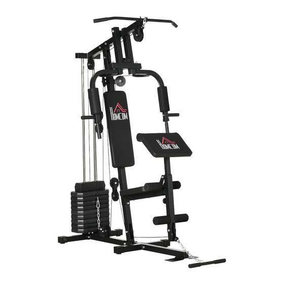
- Page 1 INald013_IT_EN A91-177 *Il peso massimo dell'utente è di 100 Kg. IMPORTANT, RETAIN FOR FUTURE REFERENCE: READ CAREFULLY ASSEMBLY & INSTRUCTION MANUAL...
- Page 6 DIAGRAMMA ESPLOSO...
- Page 7 LISTA PARTI Parte No. Descrizione Qta’ Parte No. Descrizione Qta’ Telaio Base Dado in Nylon M10 Tubo di Supporto Montante Perno Fisso per Placche Pesi Stabilizzatore posteriore Cuscinetto Stabilizzatore anteriore Tappo Quadrato Tubo Guida Tappo Estremita‘ Tappo Sferico ⌽ 25.4 Tubo di Supporto Sedile Tubo Sollevamenti Gambe Boccola...
-
Page 8: Istruzioni Di Assemblaggio
ISTRUZIONI DI ASSEMBLAGGIO Passo 1 1) Fissare lo Stabilizzatore Posteriore (03) al Telaio Base (01) e stringere con X2 Bullone a Testa Esagonale (30), X4 Rondella (34) e X2 Dadi in Nylon (38). 2) Fissare lo Stabilizzatore Anteriore (04) al Telaio Base (01) e stringere con X2 Bullone a Testa Esagonale (30), X4 Rondella (34) e X2 Dadi in Nylon (38). - Page 9 Passo 2 1) Far scorrere entrambi i tubi guida (05) attraverso l'anello di gomma (47) nei 2 fori sullo stabilizzatore posteriore (3), stringere sul lato inferiore con una rondella ×2 (33) e un bullone a testa esagonale ×2 (22). 2) Posizionare le Placche Peso (63) nel Tubo Guida (05). (fare attenzione alla propria sicurezza) 3) Posizionare la Boccola per Placche Peso (55) sulla Barra di Selezione (12) e fissata dal Perno (40).
- Page 10 Passo 3 1) Posizionare il Tubo Guida (05) nel Tubo Ponte (08) e stringere con la Rondella Piatta X2 (33) e il Bullone a Testa Esagonale X2 (22). 2) Fissare la Traversa (08) al Tubo di Supporto Montante (02) e stringere con X2 Bullone a Testa Esagonale (30), X4 Rondella Piatta (34) e X2 Dadi in Nylon (38).
- Page 11 Passo 4 1) Fissare il Tubo di Supporto Sedile (06) al Tubo di Supporto Montante (02), stringere con il Bullone a Testa Esagonale X2 (30), la Rondella X4 (34) e i Dadi in Nylon X2 (38). 2) Fissare il Cuscino dello Schienale (57) al Tubo di Supporto Montante (02), stringere con il Bullone a Testa Esagonale X2 (25) e la Rondella Piatta X2 (34) e far passare dai fori filettati sul Cuscino dello Schienale (57).
- Page 12 Passo 5 1) Fissare il Set Trazioni (09) alla Traversa (08), inserire l‘Asse per Set Trazioni (19) attraverso l'Anello di metallo X4 (31), la Rondella piatta X2 (35) e stringere con i Dadi in nylon X2 (39) . 2) Fissare il Braccio Destro R (10R) al lato destro del Set Trazioni (09) attraverso X2 Anello di Metallo (31) e X1 Rondella Piatta (35) e stringere con X1 Dado in Nylon (39).
- Page 13 Passo 6 1)Fissare il Cavo per Barra Dorsale (66) nell'apertura della staffa nella parte anteriore della Traversa (8) Nota: il morsetto a sfera del Cavo (66) dovrebbe trovarsi sotto la Traversa (8). Fissare il Cavo (66) sulla Puleggia Piccola (49). Nota: Il Cavo (66) deve fuoriuscire dal Tappo (50) dai lati aperti.
- Page 14 Passo 7 1) Fissare un'estremità del Cavo per Braccio (64) al gancio sul Braccio Destro (10R), stringere con il Bullone a Testa Esagonale X1 (22), la Rondella Piatta X1 (33) e il Dado in Nylon X1 (37). 2) Tirare il Cavo (64) attorno alla Puleggia (48), quindi fissare la Puleggia (48) al Supporto Puleggia (17) sul lato destro del Tubo di Supporto Montante (2), stringere con il Bullone a Testa Esagonale X1 (26) e Dado in nylon X1 (38).
- Page 15 Passo 8 1) Fissare l'estremità con il morsetto a sfera del Cavo per Barra di Trazione Inferiore (65) al Tubo per Sollevamento Gambe (7), attorno al lato inferiore della Puleggia (48), stringere la Puleggia (48) con la staffa con X1 Bullone a Testa Esagonale (28) attraverso la boccola in plastica X2 (46) (ogni lato), rondella X2 (24) (una per lato) e il Dado in Nylon X1 (38).
- Page 16 Avvertenza: assicurarsi che tutti i bulloni e i dadi in nylon siano suffici- entemente stretti prima di utilizzare il macchinario. TRAZIONI DORSALI PRESSA PETTORALI TRAZIONI BICIPITI ESTENSIONI GAMBE PRESSA TRICIPITI ADDOMINALI A.B. VOGATORE CROCI PETTORALI...
- Page 17 INald013_IT_EN A91-177 *The maximum user weight is 100 Kg. IMPORTANT, RETAIN FOR FUTURE REFERENCE: READ CAREFULLY ASSEMBLY & INSTRUCTION MANUAL...
-
Page 22: Exploded Diagram
EXPLODED DIAGRAM... -
Page 23: Parts List
PARTS LIST... - Page 24 ASSEMBLY INSTRUCTIONS STEP 1 1) Attach the Rear Stabilizer (03) to the Base Frame (01) and tighten by X2 Hex Head Bolt (30), X4 Washer (34) and X2 Nylon Nuts (38). 2) Attach the Front Stabilizer (04) to the Base Frame (01) and tighten by X2 Hex Head Bolt (30), X4 Washer (34) and X2 Nylon Nuts (38).
- Page 25 STEP 2 1) Slide both Guiding Tube (05) through Rubber Ring (47) into the 2 holes on the Rear Stabilizer (3), tighten from the bottom side by X2 Washer (33) and X2 Hex Head Bolt (22). 2) Place the Weight Stack (63) into the Guiding tube (05). (Watch out personal safety) 3) Place the Bushing for Weight Stack (55) onto the Select Bar (12) and fixed by the Fixed Pin (40).
- Page 26 STEP 3 1) Place the Guiding Tube (05) into the Bridge Tube (08) and tighten by X2 Flat Washer (33) and X2 Hex Head Bolt (22). 2) Attach the Bridge Tube (08) to the Upright Support Tube (02) and tighten by X2 Hex Head Bolt (30), X4 Flat Washer (34) and X2 Nylon Nuts (38).
- Page 27 STEP 4 1) Attach the Seat Support Tube (06) to the Upright Support Tube (02), tighten by X2 hex Head Bolt (30), X4 Washer (34) and X2 Nylon Nuts (38). 2) Attach Backrest Cushion (57) into Upright Support Tube(02), tighten by X2 Hex Head Bolt (25) and X2 Flat Washer (34) through the thread holes on the Backrest Cushion (57).
- Page 28 STEP 5 1) Attach the Pull Unit (09) to the Bridge Tube (08), insert the Axle for Pull Unit (19) throughX4 Powder Metal Ring (31), X2 Flat Washer (35) and tighten by X2 Nylon Nuts (39). 2) Attach the Butterfly Arm R (10R) to the right side of Pull Unit (09) through X2 Powder Metal Ring (31) and X1 Flat Washer (35) and tighten by X1 Nylon Nut (39).
- Page 29 STEP 6 1) Attach the Cable for Lat Bar (66) to the opening bracket at the front of the Bridge Tube (8). Note: The ball stopper of the Cable (66) should be underneath the Bridge Tube (8). Attach the Cable (66) onto the Small Pulley (49) and . Note: The Cable (66) has to come out of the Cap (50) from the opening sides.
- Page 30 STEP 7 1) Attach one end of the Cable for Butterfly Arm (64) to the hook on the Right Butterfly Arm (10R), tighten by X1 Hex Head Bolt (22), X1 Flat Washer (33) and X1 Nylon Nut (37). 2) Draw the Cable (64) around the Pulley (48) then attach the Pulley (48) to the Pulley Bracket (17) on right side of the Upright Support Tube (2), tighten by X1 Hex Head Bolt (26) and X1 Nylon Nut (38).
- Page 31 STEP 8 1) Attach the end with stopper ball of Cable for Lower Pull Bar (65) to the open bracket of Leg Curl (7), around the under side of Pulley (48), tighten the Pulley(48) with the bracket by X1 Hex Head Bolt (28) through X2 Plastic Bushing (46) (each side), X2 Falt washer(24) (each side) and X1 Nylon Nut (38).
- Page 32 Warning: Make sure all bolt and nylon nut are tighten enough before using the machine.
Need help?
Do you have a question about the A91-177 and is the answer not in the manual?
Questions and answers