
Related Manuals for HOMCOM A91-106


Summary of Contents for HOMCOM A91-106
- Page 1 INade074_UK A91-106 Heavy Duty Adjustable Power Tower READ AND SAVE THIS INSTRUCTION FOR FUTURE USE...
-
Page 2: Warning Decal Placement
WARNING DECAL PLACEMENT This drawing shows the location(s) of the warning decal(s). If a decal is missing or illegible, see the front cover of this manual and request a free replacement decal. Apply the decal in the location shown. Note: The decal(s) may not be shown at actual size ury pos dy p... -
Page 3: Important Precautions
IMPORTANT PRECAUTIONS WARNING: To reduce the risk of serious injury, read all important precautions and instructions in this manual and all warnings on your exercise rack before using your exercise rack. assumes no responsibility for personal injury or property damage sustained by or through theuse of this product. -
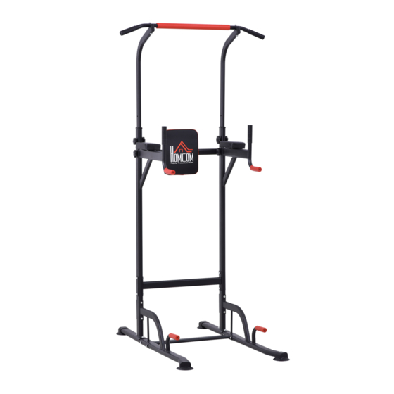
Page 4: Before You Begin
BEFORE YOU BEGIN Thank you for selecting the versatile POWER reading this manual, please see the front TOWER exercise rack. The POWER TOWER exercise cover of this manual. rack is designed to help you develop the major muscle grou ps of the upper body. Whether your goal is a Before reading further, please review the shapely figure, dramatic muscle size and strength, or a drawing below and familiarize yourself with... -
Page 5: Part Identification Chart
PART IDENTIFICATION CHART Use the drawings below to identify the small parts needed for assembly. The number in parentheses below each drawing is the key number of the part. Note: If a part is not in the hardware kit, check to see if it has been preassembled. Extra parts may be included. - Page 6 Specificati Parts list Name picture Quantity Arc backing 13*3 plate Reinforced 13*3 backing plate Circular gasket Arc gasket hexagonal installationtoo wrench ACCESSORłES DETAłLS Name picture Quantity Base bracket Main frame Auxiliary pipe Auxiliary pipe Foot connecting tube...
- Page 7 Name picture Quantity Single pole Backrest pipe Back cushion Elbow pads ASSEMBLY After confirming the integrity of all accessories, start installation NOTE : PLEASE DO NOT SECURELY TIGHTEN ALLBOLTS UNTIL STEP 9. Step 1 ① Identify the left and right base(A)
- Page 8 Step 2 Connect Base (A) and Foot Pipe (D) ① Connect the two foot tubes (D) and base (A) with the four M8*70 inner hexago- nal screws (2) then, tighten arc plate (9) to them with M8 (8) locknuts. Step 3 Install Main Frame ①...
- Page 9 Step 4 Install Main Frame ① Find the supervisor joint(E) with 4 M8 * 40 inner hexagonal screws(4), connect with the main frame(B) put the reinforcement pad(10) through from the outside, and tighten with the M8 nut(8). Step 5 Install Elbow Pad(L) ①...
- Page 10 Step 6 Installation of cushions(H) ① Attach the backrest pad (H)to the backrest pipe(G) with the screws of the backrest pipe(G). Step 7 Install backend(C) ① Attach the backrest tube (G) to the main frame (B) with the M8*15 inner hex- agonal screw (5) then, tighten round plate(11) to them with the inner hexago- nal wrench.
- Page 11 Step 8 Install single bar(F) ① Attach the single rod (F) to the auxiliary pipe (C) with M8*80 inner hexagonal screws (3) then, tighten arc plate(12) to them with M8 (8) locknuts. Note: Orient the Screw holes Step 9 Install Deputy(C) ①...
-
Page 12: Installation Complete
INSTALLATION COMPLETE... - Page 13 EXPLODED DRAWłNG...
-
Page 14: Exercise Guidelines
EXERCISE GUIDELINES Warm-Up The purpose of warming up is to prepare your body for exercise and to minimize injuries. Warm up for two to five minutes before strength training or aerobic exercising. Perform activities that raise your heart rate and warm the working muscles. - Page 15 Floor Stretch While sitting on the floor, open the legs as wide as possible. Stretch the upper body toward the knee on the right leg by using your arms to pull your chest to your thighs. Hold this stretch 10 to 30 seconds. DO NOT BOUNCE! Do this stretch 10 times.
Need help?
Do you have a question about the A91-106 and is the answer not in the manual?
Questions and answers