Table of Contents
Advertisement
Quick Links
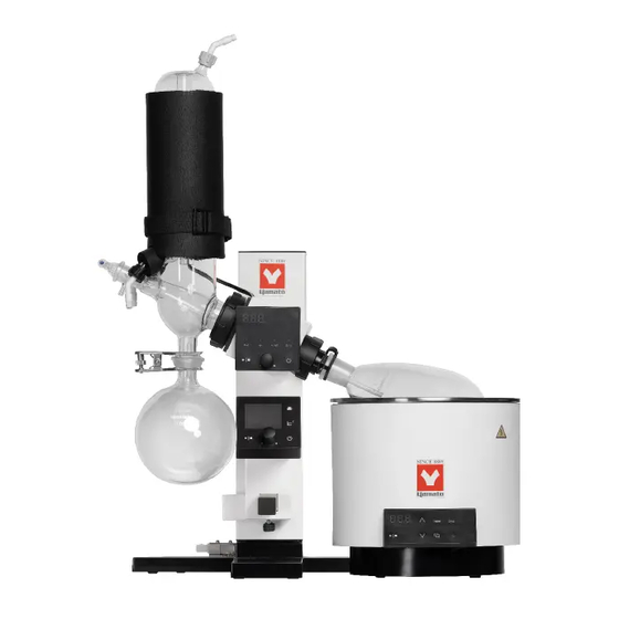
Rotary Evaporator
REV202M series
Instruction Manual
Thank you for choosing REV202M series Rotary
Evaporator from Yamato Scientific Co., Ltd.
●For proper equipment operation, please read and
become thoroughly familiar with this instruction manual
before use. Always keep equipment documentation safe
and close at hand for convenient future reference.
Warning : Read instruction manual warnings and
cautions carefully and completely before
proceeding. Read instruction manual thoroughly
before operation.
Yamato Scientific Co. Ltd.
First Edition
Printed on recycled paper
Advertisement
Table of Contents

Related Manuals for Yamato REV202M Series


Summary of Contents for Yamato REV202M Series
- Page 1 Rotary Evaporator REV202M series Instruction Manual First Edition Thank you for choosing REV202M series Rotary Evaporator from Yamato Scientific Co., Ltd. ●For proper equipment operation, please read and become thoroughly familiar with this instruction manual before use. Always keep equipment documentation safe and close at hand for convenient future reference.
-
Page 3: Table Of Contents
TABLE OF CONTENTS REV202M Series Product Line-Up ....................2 1. SAFETY PRECAUTIONS ......................1 Explanation of Symbols ......................1 Symbol Glossary ........................2 Warnings and Cautions ......................3 Wireless Interlocking ........................5 List of Residual Risks ........................ 6 2. COMPONENT NAMES AND FUNCTIONS .................. 8 Main Unit ............................ - Page 4 Maintenance and Inspection ....................46 7. EXTENDED STORAGE AND DISPOSAL .................. 47 Extended Storage/Disposal ..................... 47 Disposal Considerations ......................47 8. TROUBLESHOOTING ........................ 48 Reading Error Codes (Control Panel 1) ................... 48 Reading Error Codes (Control Panel 2) ................... 49 Troubleshooting Guide ......................
- Page 7 ・ ・ ・ ・ Ԃ Ԃ...
- Page 8 ・ ・ ・ ・ ・ Ԃ ・ Ԃ...
- Page 9 : R 201-190693 ① ② ③ ・ ・ ・ ・...
-
Page 10: Safety Precautions
1. SAFETY PRECAUTIONS List of Residual Risks List of residual risks (instructions for risk avoidance) This list summarizes residual risks to avoid personal injuries or damages to properties during or related to the use of equipment. Be sure to fully understand or receive instructions on how to use, maintain and inspect equipment before starting operation. - Page 11 1. SAFETY PRECAUTIONS List of Residual Risks Daily inspection/maintenance Degree of Risk Protective measures taken by the user Relevant risks description page Fire/Electric Be sure to disconnect power cable before daily WARNING P.46 shock inspection and maintenance. Fire/Electric WARNING NEVER disassemble or modify unit P.46 shock Extended storage/disposal...
-
Page 12: Component Names And Functions
Evaporation Flask Jack handle Stand base Bath guide VR connection terminal (mini-DIN 8P) DC jack AC adapter Vacuum control solenoid valve Level adjuster Power cable * Type of plug differs by models. See “ REV202M Series Product Line-Up ” for details. - Page 13 VR connection terminal (mini-DIN 8P) Sample feed stopcock DC jack Sample inlet Cooling nozzle (black cap)(OUT) AC adapter Vacuum control solenoid valve Level adjuster Power cable * Type of plug differs by models. See “ REV202M Series Product Line-Up ” for details.
-
Page 14: Accessories
② AC adapter ③ Bath guide ④ Rear cover (approx. 3 m) ⑤ Tape fastener ⑥ Joint nut ⑦ Exhaust hose ⑧ REV202M series (For purging) Instruction Manual ⑨ VR102S series Instruction Manual ⑩ Warranty card *1 Used for binding codes and hoses φ7.94 ×... - Page 15 ① ⑧ ⑦ ⑨ ⑥ AutoR Sync ④ ② ③ ⑤ ① ② Ԃ ③ ④ ⑤ ⑥ ⑦ ⑧ ⑨...
- Page 16 ④ ① ⑤ ② ⑥ ③ ① ② ③ ④ ⑤ ⑥ Ԃ...
- Page 17 ③ ② ① ④ ⑦ ⑤ ⑧ ⑥ ⑨ ① ・ ・ ・ ② ③ ④ ⑤ ① ② ③ ④ ⑤ ⑥ ⑦ ⑧ ⑨...
- Page 18 Vacuum control solenoid valve *1 Vacuum pump REV202M series *1: Vacuum control solenoid valve is embedded in the back of main unit.
- Page 19 AC vacuum pump *2 REV202M series *1: Vacuum control solenoid valve is embedded in the back of main unit. *2: Applicable AC pump: Yamato Scientific PG201, ULVAC DTC-22/DTC-41, KNF N810/N820/N840 REV202M-A, REV212M-A, REV212M-B, and REV212M-D cannot be connected with Vacuum pump control unit.
- Page 20 ・ ・ where flammable or corrosive gases/fumes may be present ・ where external temperature will exceed 35 °C, will fall below 5 °C or will fluctuate largely. ・ where liquid is assumed to splash on unit ・ in excessively humid or dusty locations. ・...
- Page 22 Operational voltage range is ±10 % of power rating, performance guarantee voltage range is ±5 %, and frequency is ±1 % * Check the line voltage on distribution board and properly evaluate whether to utilize a line being shared by other equipment. If unit is not activated by turning ON (|) power, take an appropriate course of action, such as connecting unit to a dedicated power source.
-
Page 25: Solenoid Valve
3. PRE-OPERATION PROCEDURES Installation Procedure 4. Connecting cables and tubing * Ensure that the tubing is not loose or disconnected. (1) Connect the PTFE tube protruding from the PTFE tube back of main unit to the fitting of the vacuum control solenoid valve, and connect connection Connection cable for cable, with the hook facing up, to the connector... -
Page 26: Installation Procedure
3. PRE-OPERATION PROCEDURES Installation Procedure 4. Connecting cables and tubing (3) Slide supplied rear cover over the post along its groove. Draw power cable and connection cable through the U-notch in the bottom of rear cover. Rear cover * Exercise caution not to pinch power cable, connection cable, and solenoid valve cable in the rear cover when attaching it. - Page 27 3. PRE-OPERATION PROCEDURES Installation Procedure 5. Installing rotary joint (1) Remove joint nut Press in the lock pin with the thumb to lock the rotary part. Take off joint nut by turning it counterclockwise with the other hand. Lock pin Joint nut (2) Install rotary joint Insert rotary joint into the rotary joint opening...
- Page 28 ① ② ② ① ③...
- Page 29 ① ②...
- Page 30 ① ②...
- Page 31 3. PRE-OPERATION PROCEDURES Installation Procedure 11. Installing condenser bracket (only for vertical condenser, type B) * Use vertical condenser (type B) in conjunction with condenser bracket Hex wrench (included) included with glass set B. Motor box (1) Remove two cap bolts (black) on motor box with supplied hex wrench.
- Page 34 3. PRE-OPERATION PROCEDURES Installation Procedure 13. Connecting vacuum/cooling hose * Vacuum hose is not included. Please prepare optional vacuum hose (product code: 255297) separately. (1) Connect vacuum nozzle and the inlet of a pressure reducing device with a vacuum hose. * Be cautious not to connect vacuum nozzle to the exhaust port of the pressure reducing device.
- Page 36 3. PRE-OPERATION PROCEDURES Installation Procedure 15. Connection of rotary evaporator and vacuum controller * The vacuum controller is connected at the time of shipment. If interlock function does not work, or any other symptoms occur, refer to this instructions to rework the connection. This product is comprised of rotary evaporator and vacuum controller, connected with a VR connection terminal...
- Page 37 ① Ԃ AutoR Sync ① ① ② AutoR Sync ③ ② ① ③ ① ② ③ ② ① ③...
- Page 38 AutoR Sync...
-
Page 39: Operation Procedures
4. OPERATION PROCEDURES User Setting (Control Panel 1) List of user setting items • Press and hold the Control knob for two seconds. User setting items will be shown. Select an item by turning the Control knob . Press the Control knob again to edit the displayed item. •... - Page 40 4. OPERATION PROCEDURES Rotation Mode (Control Panel 1) Set rotation direction F.ro: Forward rotation mode r.ro: Reverse rotation mode Ato: Timed auto inversion mode Default setting is “F.ro” 1. Enter user setting ① Press the Power key. ② Press the Control knob for two seconds while current rpm is on the screen.
- Page 41 4. OPERATION PROCEDURES Auto Inversion Time Setting (Control Panel 1) Set time interval for auto inversion mode. Setting range: 5-999 sec Default setting is “5” 1. Enter user setting ① Press the Power key. ② Press the Control knob for two seconds while current rpm is on the screen.
-
Page 42: Auto-Resume Function (Control Panel 1)
4. OPERATION PROCEDURES Auto-resume Function (Control Panel 1) Select recovery mode for the event of a power failure. OFF: Unit goes into idle at power recovery. ON: Unit automatically reverts to status just before power loss and begin operation once again from that point. -
Page 43: Led Brightness Setting (Control Panel 1)
4. OPERATION PROCEDURES LED Brightness Setting (Control Panel 1) Change the LED brightness of the control panel. The brightness can be set in 8 levels from 0 to 7. Default setting is “3” 1 Enter user setting ① Turn ON (|) power ②... -
Page 44: Vacuum Controller Connection (Control Panel 1)
4. OPERATION PROCEDURES Vacuum Controller Connection (Control Panel 1) Make connection setting with vacuum controller. OFF: Not linked (does not carry out communication) ON: Linked (carries out communication) Default setting is “ON” While connection is “ON”, operation start/stop on RE unit and vacuum controller are interlocked. 1 Enter user setting ①... -
Page 45: Start Operation
4. OPERATION PROCEDURES Start Operation Water bath BM302 series Sample feed stopcock Oil bath BO302 series Sample inlet (1) Run water bath, oil bath, or cooling water circulator at desired temperature. (2) Turn ON the control panels 1 and 2. (3) Rotate sample feed stopcock to close sample inlet. -
Page 46: Operation Stop
4. OPERATION PROCEDURES Operation Stop (1) Press the Run/Stop key on the control panel 1 or control panel 2 to stop rotation and Run/Stop key decompression. When auto leak function of the vacuum controller is turned on, the leak valve will open. When auto cleaning is enabled, cleaning will start after the preset time for auto leak function. - Page 47 4. OPERATION PROCEDURES Stop Operation (6) Remove condenser fixing band. * Only for Condenser nut vertical condenser (type B) (7) Hold cooling condenser by hand and turn condenser nut counterclockwise. Remove cooling condenser. Turn counterclockwise to loosen...
- Page 48 Ԃ Ԃ...
- Page 50 ◆...
- Page 51 Ԃ ...
- Page 52 8. TROUBLESHOOTING Reading Error Codes (Control Panel 1) Unit has a self-diagnostic function built into the CPU board. The table below shows possible causes and measures to take when safety function is performed. [Error Codes] When an operational error or malfunction occurs, an error code is displayed on the control panel. When an error occurs, confirm the error code and terminate operation immediately.
- Page 53 for details. Ԃ Ԃ Ԃ ● ● Ԃ Ԃ ● Ԃ Ԃ ● Ԃ Ԃ Ԃ Ԃ ● Ԃ...
- Page 54 8. TROUBLESHOOTING Troubleshooting Guide Troubles Symptom Possible causes Possible measures ● ● RPM display remains Power supply failure Regulate the supply voltage to the rated blank when the Power ● voltage of unit AC adapter failure key is pressed. ● ●...
- Page 55 8. TROUBLESHOOTING Troubleshooting Guide ● ● Rotary joint cannot be Rotary joint lock mechanism is Gentry tap rotary joint with plastic head pulled out stuck, worn or deteriorated hammer to remove. Use caution not to break the rotary joint ● Replace relevant parts (call for service) ●...
- Page 56 Warranty card (attached separately) Warranty card will be handed by dealer or Yamato personnel upon delivery and installation, or will be attached to equipment if no one from dealer or Yamato is to be present at delivery and installation. Register warranty card at https://www.yamato-net.co.jp/support/warranty.htm ●...
- Page 57 Approx. 10.5 kg (including cooling condenser) [Main unit] REV202M series instruction manual (1), VR102S series instruction manual (1) Warranty card (1) *4 AC adapter (1),Power cable (1),Bath guide Rear cover (1), Tape fastener (single-sided) (1 roll), Tape fastener (double-sided) (1 roll)
- Page 58 10. SPECIFICATIONS List of Consumable Parts Some components attached or built into this unit with different lifespans, depending on the use conditions, and environment are regarded as consumables. It is recommended to replace these parts as needed. The components listed below are not covered by the warranty. [Consumables/replacement parts for main unit] ①...
- Page 59 ㉑ ㉒ ⑩ ㉓ ⑨ ⑳ ⑲ ⑧ ⑰-A ㉔ ⑱ ⑦ ⑯ ⑤ ④ ① ③ ⑫ ② ⑭ ㊶ ⑬ ㊷ ㊵ ⑮ ⑥ ⑲ ⑩ ㉑ ⑪ ⑨ ⑰-B ⑰-E ⑳ ㉔ ⑧ ⑱ ㉒ ⑯ ⑦ ②...
- Page 60 ② ⑥ ⑦ ⑩ ⑪ ㊴ ⑨ ⑧ ⑫ ① ④ ③ ⑤ ⑬ ⑭ ⑮ ⑯...
- Page 61 11. OPTIONAL ACCESSORIES Consumables/Replacement Parts/Options [Consumables/replacement parts for main unit] ㊵ Vacuum control ㊷ VR attachment ㊸ Connection cable ㊹ Exhaust hose solenoid valve bracket (For purging) Product code Part code Product code Part code 255762 REV02S0010 LT00040442 ORT12S0001 VR102S connection Fittings and knurled For VR102S/RE202 φ7.94 ×...
- Page 62 11. OPTIONAL ACCESSORIES List of Options [Consumables/replacement parts for glass set] ⑰-A Cooling condenser ⑰-B Cooling condenser ⑰-E Cooling condenser ⑱ Sample feed stopcock type A type B type E Product code: 255750 Product code: 255751 Product code: 255753 Product code: 255738 Condenser insulation kit, Condenser insulation kit, Condenser insulation kit,...
- Page 63 ㉜ ㉝ ㉞ ㉟ 150 × 150 mm 200 × 200 mm Height 75-245 mm Height 75-245 mm ㊱ ㊲ ㊳ Ă 24/40 24/40 24/40 29/38 29/38 29/38 29/38 Ă Ă Ă Ă Ă Ă Ă 24/40 19/38 15/25 24/40 19/38 15/25 29/38...
- Page 64 Can be installed onto N820G. be controlled via VR102S by Stand. ■ Applicable vacuum pump installing OVR26. ■ Applicable AC pump Yamato Scientific N820G Yamato Scientific PG201 ULVAC DTC-22, DTC-41 KNF: N810, N820, N840 ④ Stand ⑤ Exhaust trap kit ⑥...
- Page 65 12. REFERENCE DATA Solvent Boiling Point Substance Chemical Molecul Density Latent heat Boiling Degree of vacuum at each formula (g/cm point (°c) boiling point (hPa) weight (20 °C) vaporization Boiling Point (cal/g) (1013 hPa) 25 °C 30 °C 40 °C (1013 hPa) Diethyl ether 74.1...
- Page 66 13. LIST OF HAZARDOUS SUBSTANCES Table 13.1 List of hazardous substances ①Nitroglycol, Glycerine trinitrate, Cellulose Nitrate and other explosive nitrate esters ②Trinitrobenzen, Trinitrotoluene, Picric Acid and other explosive nitro compounds ③Acetyl Hydroperoxide, Methyl Ethyl Ketone Peroxide, Benzoyl Peroxide and other organic peroxides ④Metallic Azide, including Sodium Azide, etc.
-
Page 67: Handling Precautions
14. STANDARD INSTALLATION MANUAL Install this equipment according to following format (check options and special specifications separately). Charged Personnel or Installation proved Model Serial Number Installation Date Company Name for Judgment Installation № Item Implementation method Chapter No. & Reference page of Judgment instruction manual Specifications... - Page 68 Always operate equipment in strict compliance to the handling and operation procedures set forth by this instruction manual. Yamato Scientific Co., Ltd. assumes no responsibility for malfunction, damage, injury or death resulting from negligent equipment use. Never attempt to disassemble, repair or perform any procedure which are not expressly mandated by this manual.
Need help?
Do you have a question about the REV202M Series and is the answer not in the manual?
Questions and answers