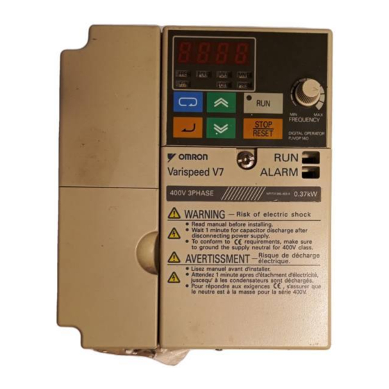
Omron VARISPEED V7 User Manual
Varispeed v7 compact sensorless vector inverter
Hide thumbs
Also See for VARISPEED V7:
- Quick manual (162 pages) ,
- Manual (23 pages) ,
- Brochure & specs (21 pages)

Related Manuals for Omron VARISPEED V7


Summary of Contents for Omron VARISPEED V7
- Page 1 Manual No. TOEPC71060605-02-OY VARISPEED V7 Compact Sensorless Vector Inverter USER’S MANUAL...
-
Page 2: General Precautions
Such modifications are indicated by revising the manual number. • To order a copy of this manual, or if your copy has been damaged or lost, contact your OMRON representative. • OMRON YASKAWA is not responsible for any modification of the product... -
Page 3: Notation For Safety Precautions
NOTATION FOR SAFETY PRECAUTIONS Read this instruction manual thoroughly before installation, operation, mainte- nance, or inspection of the V7AZ. In this manual, safety precautions are classi- fied as either warnings or cautions and are indicated as shown below. WARNING Indicates a potentially hazardous situation which, if not avoided, may result in death or serious injury. - Page 4 Confirm that all indicators are OFF before proceeding. • Do not perform a withstand voltage test on any part of the Inverter. The Inverter is an electronic device that uses semiconductors, and is thus vul- nerable to high voltage.
- Page 5 CAUTION (Ref. page) • Lift the Inverter by the heatsinks. When moving the Inverter, never lift it by the plastic case or the terminal cover. Otherwise, the main unit may fall and be damaged. • Mount the Inverter on nonflammable material (i.e., metal).
- Page 6 Failure to observe this warning may result in an elec- tric shock or a fire. • For 400 V Class, make sure to ground the sup- ply neutral. Failure to observe this warning may result in an elec- tric shock or a fire.
- Page 7 • Verify that the Inverter rated voltage coincides with the AC power supply voltage. Failure to observe this caution may result in personal injury or a fire. • Do not perform a withstand voltage test on the Inverter. Performing withstand voltage tests may damage semiconductor elements.
- Page 8 OPERATION WARNING (Ref. page) • Only turn ON the input power supply after con- firming that the Digital Operator or blank cover (optional) are in place. Do not remove the Digital Operator or the covers while current is flowing. Failure to observe this warning may result in an elec- tric shock.
- Page 9 WARNING (Ref. page) • If an alarm is reset with the operation signal ON, the Inverter will restart automatically. Reset an alarm only after verifying that the operation sig- nal is OFF. Failure to observe this warning may result in injury.
- Page 10 CAUTION (Ref. page) • If using an Inverter with an elevator, take safety measures on the elevator to prevent the eleva- tor from dropping. Failure to observe this caution may result in injury. • Do not perform signal checks during operation.
- Page 11 WARNING (Ref. page) • Never touch high-voltage terminals on the Inverter. Failure to observe this warning may result in an elec- trical shock. • Disconnect all power before performing mainte- nance or inspection, and then wait at least one minute after the power supply is disconnected.
- Page 12 Failure to observe this caution may result in injury. OTHERS WARNING • Never modify the product. Failure to observe this warning may result in an electrical shock or injury and will void the guarantee. CAUTION • Do not subject the Inverter to halogen gases, such as fluorine, chlorine, bromine, and iodine, at any time even during trans- portation or installation.
-
Page 13: Warning Label
WARNING LABEL A warning label is provided on the front cover of the Inverter, as shown below. Follow the warnings when handling the Inverter. Plastic Case Status Indicators Nameplate Warning Label Location Certification Mark Warning Labels FPST31042-8 FPST31042-74 Example of 5.5 kW for 400 V... -
Page 14: Table Of Contents
Test Run - - - - - - - - - - - - - - - - - - - - - - - - - - - - - - - - - - - - - -... - Page 15 6 Programming Features - - - - - - - - - - - - - - - - - - 52 Hardware - - - - - - - - - - - - - - - - - - - - - - - - - - - - - - - - - - 52...
- Page 16 Slip Compensation (n002 = 0) - - - - - - - - - - - - - - - - - - 135 Motor Protection - - - - - - - - - - - - - - - - - - - - - - - - - - - - - - - - 136...
- Page 17 Software No. Display - - - - - - - - - - - - - - - - - - - - - - - - - 178 Display List - - - - - - - - - - - - - - - - - - - - - - - - - - - - - - - - 179...
- Page 18 10 Conformance to CE Markings - - - - - - - - - - - - 247 CE Markings - - - - - - - - - - - - - - - - - - - - - - - - - - - - - - - - - - 247...
-
Page 19: Receiving The Product
After unpacking the V7AZ, check the following. • Verify that the model number matches your purchase order or packing slip. • Check the Inverter for physical damage that may have occurred during shipping. If any part of V7AZ is missing or damaged, call for service immediately. -
Page 20: Checking The Nameplate
Inverter Software Version The inverter software version can be read out from the monitor parameter U-10 or parameter n179. The parameter shows the last for digits of the software number (e.g. display is“5740”for the software version VSP015740). The manual describes the functionality of the Inverter software version VSP015740 (0.1 to 4.0 kW) and VSP105750 (5.5 and 7.5 kW). -
Page 21: Identifying The Parts
(without potentiometer) In models without a JVOP-140 JVOP-147 Digital Operator, the Used for setting or Used for setting or blank cover is mounted changing constants. changing constants. in place of the Digital Frequency can be set Operator. using the potentiometer. - Page 22 Voltage/Current Change Switch for Analog Frequency Reference Input Short-circuit Control Circuit Terminal Block Main Circuit Terminal Block Ground Terminals Example for 3-phase (200 V Class, 1.5 kW) Inverter Frequency-setting Potentiometer Inverter Operation Status Indicators Terminal Resistor Switch for Communication Circuit Input Polarity...
- Page 23 Main Circuit Terminal Arrangement The terminal arrangement of the main circuit terminals depends on the Inverter model. CIMR-V7AZ20P1 to 20P7, B0P1 to B0P4 CIMR-V7AZ21P5, 22P2, B0P7, B1P5, 40P2 to 42P2 CIMR-V7AZ24P0, B2P2, 43P0, 44P0 CIMR-V7AZB4P0 CIMR-V7AZ25P5, 27P5, 45P5, 47P5 R/L1 S/L2 T/L3...
-
Page 24: Mounting
• Extreme cold and heat. Use only within the specified ambient tem- perature range: −10 to 50 °C (14 to 122 °F) for IP20 (open chassis type), −10 to 40 °C (14 to 105 °F) for NEMA 1 (TYPE 1) •... -
Page 25: Mounting Dimensions
7.5 kW • Lift the Inverter by the heatsinks. When moving the CAUTION Inverter, never lift it by the plastic case or the termi- nal cover. Otherwise, the main unit may fall and be damaged. • The V7AZ generates heat. For effective cooling,... -
Page 26: Mounting/Removing Components
NOTE Enclosed Wall-mounted (NEMA 1) Inverters. • Always remove the top and bottom covers before install- ing a 200 or 400 V Class Inverter with an output of 5.5/7.5 kW in a panel. Mounting/Removing Components Removing and Mounting the Digital Operator and Covers... -
Page 27: Mounting The Terminal Cover
Removing the Digital Operator After removing the front cover, (fol- low the procedure on page 25) lift the upper and lower sides (section C) of the right side of the Digital Operator in direction 1. -
Page 28: Mounting The Bottom Cover
3 Mounting Removing the Bottom Cover • 200 V class Inverters with 1.1 kW and more and all 400 V class Inverters: After removing the front cover and the terminal cover, tilt the bottom cover in direction 1 with section A as a supporting point. -
Page 29: Wiring
• When wiring the emergency stop circuit, check the wiring thoroughly before operation. Failure to observe this warning may result in injury. • For the 400 V Class, make sure to ground the supply neutral. Failure to observe this warning may result in an electric shock or a fire. - Page 30 Inverter carrier frequency. For details, refer to Carrier Frequency Selection (n080)14kHz max on page 3. Control wiring must be less than 50 m (164 ft) in length and must be separated from power wiring. Use shielded twisted-pair cable when inputting the frequency signal externally.
-
Page 31: Wire And Terminal Screw Sizes
× Wire resistance (Ω/km) × Wiring distance (m) × Current (A) × 10 Select a wire size so that voltage drop will be less than 2% of the normal rated voltage. 7. If the Inverter is connected to a power transformer exceed-... - Page 32 , +1, +2, B1, B2, (22.13) 25P5 U/T1, V/T2, W/T3 CIMR- R/L1, S/L2, T/L3, - 5.5 to 8 10 to 8 V7ΑΖ , +1, +2, B1, B2, (22.13) 27P5 U/T1, V/T2, W/T3 Note: The wire size is given for copper wire at 75°C (160°F).
- Page 33 +2, B1, B2, U/T1, B4P0 V/T2, W/T3 1.2 to 1.5 2 to 8 14 to 8 (10.65 to 13.31) Note: 1. The wire size is given for copper wire at 75°C (160°F). 2. Do not use terminal T/L3 on Inverters with single-phase input.
- Page 34 -, +1, +2, B1, B2, (12.39) 45P5 U/T1, V/T2, W/T3 CIMR- R/L1, S/L2, T/L3, 5.5 to 8 10 to 8 V7ΑΖ -, +1, +2, B1, B2, (22.13) 47P5 U/T1, V/T2, W/T3 Note: The wire size is given for copper wire at 75°C (160°F).
-
Page 35: Wiring The Main Circuits
Always connect the power supply line to input terminals R/L1, S/L2, and T/L3. Never con- nect them to terminals U/T1, V/T2, W/T3, B1, B2, −, +1, or +2. The Inverter may be dam- aged if the wrong terminals are connected. - Page 36 • Inverter Output Connect the motor terminals to U/T1, V/T2, and W/T3. • Wiring the Main Circuit Terminals Pass the cables through the wiring hole to connect them. Always mount the cover in its original position. Connect with a Phillips screwdriver.
-
Page 37: Wiring The Control Circuits
Refer to pages 126 and 142 for SW2. Wiring the Control Circuit Terminals Screwdriver Blade Width 2.5 mm max 0.4 mm max (0.098 in.) (0.016 in.) Insert the wire into the lower part of the terminal block and connect it tightly with a screwdriver. -
Page 38: Wiring Inspection
• Refer to Page 30 for tightening torques. 5.5 mm (0.22 in.) The wire sheath strip length must be 5.5 mm (0.22 in.). Open the front cover and verify that the strip length is 5.5 mm (0.22 in.). 5.5mm Scale... -
Page 39: Operating The Inverter
5 Operating the Inverter The Control Mode Selection (n002) is initially set to V/f control mode. • Only turn ON the input power supply after confirm- WARNING ing that the Digital Operator or blank cover (optional) are in place. Do not remove the Digital Operator or the covers while current is flowing. -
Page 40: Test Run
= 1 --- Enables Frequency Reference 1 (constant n024). Selection = 2 --- Enables a voltage reference (0 to 10 V) at the control circuit terminal. = 3 --- Enables a current reference (4 to 20 mA) at the control circuit terminal. - Page 41 PRGM ALARM 3. Set the following constants. PRGM n019: 15.0 (acceleration time) 15.0 n020: 5.0 (deceleration time) ALARM 4. Select forward or reverse run by press- key. (Forward) ALARM Never select REV when reverse run is prohibited. NOTE (Reverse) 60.00 5.
-
Page 42: Selecting Rotation Direction
5 Operating the Inverter Selecting Rotation Direction It is possible to select the direction in which the motor rotates when the Forward Run Command is executed. The motor rotates in the opposite direction when the Reverse Run Com- mand is executed. -
Page 43: Operating The Digital Operator
CN2-2: Operator circuit terminal (current reference) CN2-1: Operator circuit terminal (voltage reference) * For details, refer to Operator Analog Speed Reference Block Diagram on page 167. Details of Indicators (Color in parenthesis indicates the color of the indicator.) FOUT FREF... -
Page 44: Description Of Status Indicators
ALARM The following table shows the relationship between the Inverter condi- tions and the indicator on the RUN button of the Digital Operator as well as the RUN and ALARM indicators on the face of the V7AZ. The indicators are lit, unlit or flashing reflecting the order of priority. - Page 45 For details on how the status indicators function for Inverter faults, refer to Chapter 8 Fault Diagnosis. If a fault occurs, the ALARM indicator will light. The fault can be reset by turning ON the Fault Reset signal NOTE (or by pressing the...
-
Page 46: Function Indicator Description
5 Operating the Inverter Function Indicator Description By pressing on the Digital Operator, each of the function indi- cators can be selected. The following flowchart describes each function indicator. Power ON Frequency reference setting/monitoring (Hz) Sets V7AZ operating speed. Output frequency monitoring (Hz) -
Page 47: Mntr Multi-Function Monitoring
If n001=5, a Run Command can be received even WARNING while changing a constant. If sending a Run Com- mand while changing a constant, such as during a test run, be sure to observe all safety precautions. Failure to observe this warning may result in injury. - Page 48 * 3. The display range is from −99.9 to 99.99 kW. When regenerating, the output power will be displayed in units of − 0.01 kW when 9.99 kW or less and in units of 0.1 kW when more − than 9.99 kW.
-
Page 49: Input/Output Terminal Status
In vector control mode, “---” will be displayed. * 4. Applicable only for Inverters of 5.5 kW and 7.5 kW (200 V and 400 V Classes). * 5. Refer to the next page for data reception error. * 6. Displayed in units of 0.1% when less than 100% and in units of 1% when 100% or more. - Page 50 Fault History Display Method When U-09 is selected, a four-digit box is displayed. The three digits from the right show the fault description, and the digit on the left shows the order of fault (from one to four). Number 1 represents the most recent fault, and numbers 2, 3, 4 represent the other faults, in ascending order of fault occurrence.
-
Page 51: Simple Data Setting
Digital setting (refer to 5 Operating the Inverter) and potentiometer set- ting are both possible for simple acceleration/deceleration operation of the V7AZ. Digital setting is set at the factory (n004=1). For the model with JVOP- 140 Digital Operator (with potentiometer), factory setting is set by a fre- quency-setting potentiometer (n004=0). - Page 52 Data Setting by Frequency-setting Potentiometer Operation Steps Operator Function Status Display Indicators Indicators 1. Turn the potentiometer fully to the left. 0.00 FREF Then, turn the power ON. ALARM 2. F/R flashes. Select FWD/REV Run using keys. ALARM Never select REV when reverse NOTE run is prohibited.
-
Page 53: Programming Features
6 Programming Features Factory settings of the constants are shaded in the tables.After wiring is complete, be sure to make the following settings before operation. Hardware Make the following settings before the Inverter is turned ON. Item Ref. page Sequence input signal (S1 to S7) polarity selection... -
Page 54: Constant Setup And Initialization
Failure to observe this warning may result in injury. The following table lists the data that can be set or read when n001 is set. By setting this constant, the fault history can be cleared and the con- stants initialized. - Page 55 (n050 to n056) are the same 2. If the following conditions are not satisfied in the V/f pat- tern setting: Max. Output Frequency (n011) ≥ Max. Voltage Output Frequency (n013) > Mid. Output Frequency (n014) ≥ Min. Output Frequency (n016) Note: Mid.
-
Page 56: Using V/F Control Mode
Adjust motor torque by using the V/f pattern and full-range automatic torque boost settings. V/f Pattern Setting Set the V/f pattern in n011 to n017 as described below. Set each pattern when using a special motor (e.g., high-speed motor) or when requiring special torque adjustment of the machine. - Page 57 * 10.0 V (20.0 V) for Inverters of 5.5 kW and 7.5 kW (200 V and 400 V Classes).
- Page 58 6 Programming Features Typical Setting of the V/f Pattern Set the V/f pattern according to the application as described below. For 400-V Class Inverters, the voltage values (n012, n015, and n017) should be doubled. When running at a frequency exceeding 50/60 Hz, change the Maximum Output Frequency (n011).
- Page 59 Gain (n103, factory setting: 1.0). When the wiring distance between the Inverter and the motor is long, or when the motor generates vibration, change the automatic torque boost gain. In these cases, set the V/f pat- tern (n011 to n017).
-
Page 60: Using Vector Control Mode
Vector control requires motor constants. The factory settings constants have been set at the factory prior to shipment. Therefore, when a motor designed for an Inverter is used or when a motor from any other manu- facturer is driven, the required torque characteristics or speed control characteristics may not be maintained because the constants are not suit- able. -
Page 61: Motor Constant Calculation
• If the speed is less than the target value, increase the slip compensa- tion gain. • If the speed is more than the target value, reduce the slip compensa- tion gain. Adjustment of the Slip Compensation Time Constant (n112) is normally not required. -
Page 62: V/F Pattern During Vector Control
Line-to-neutral Resistance), and n110 (Motor No-load Current) accord- ing to the motor test report. To connect a reactor between the Inverter and the motor, set n108 to the sum of the initial value of n108 (Motor Leakage Inductance) and the externally mounted reactor inductance. -
Page 63: Switching Local/Remote Mode
When operating with a frequency larger than 60/50 Hz, change only the Max. Output Frequency (n011). Constant output or Constant torque variable output n012 =200 V Base point n013 n011 =60 or 50 Hz =90 Hz Switching LOCAL/REMOTE Mode The following functions can be selected by switching LOCAL or REMOTE mode. -
Page 64: How To Select Local/Remote Mode
LOCAL Mode When Lo (local mode) is selected for Digital Operator mode, or when the LOCAL/REMOTE switching function is set and the input terminals are turned ON, run operation is enabled by the STOP... -
Page 65: Remote Mode
2 (Factory setting) • For an example of three-wire sequence, refer to page 112. • For more information on how to select the sequence polarity, refer to page 226. Note: When the Inverter is operated without the Digital Operator, always set constant n010 to 0. -
Page 66: Local Mode
Factory setting of models with the Digital Operator with a potentiometer (JVOP-140) is n004=0. =2: Enables a voltage reference (0 to 10 V) (refer to the figure on page 65). =3: Enables a current reference (4 to 20 mA) (refer to page 126). -
Page 67: Setting Operation Conditions
Autotuning Selection (n139) Motor data required for vector control can be measured and set by inputting the data from the nameplate of the motor to be used and per- forming autotuning for the motor. Autotuning is possible only for motor... - Page 68 • Rotational Autotuning (n139 = 1) Rotational autotuning is used only for open-vector control. Set n139 to 1, input the data from the nameplate, and then press the RUN key on the Digital Operator. The Inverter will stop the motor for approximately 1 minute and then set the required motor constants automatically while operating the motor for approximately 1 minute.
- Page 69 • When speed precision is required at high speeds (i.e., 90% of the rated speed or higher), use a motor with a rated voltage that is 20 V less than the input power supply voltage of the Inverter for 200V- class Inverters and 40 V less for 400V-class Inverters.
-
Page 70: Operating Procedure
NOTE voltage × 0.9. 2. When operating at high speeds (i.e., 90% of the rated speed or higher), the output current will increase as the input power supply voltage is reduced. Be sure to provide sufficient margin in the Inverter current. - Page 71 Base frequency − Rated speed × Number of poles / 120 When performing precision setting (i.e., when performing autotun- ing using a motor test report or design data), the input data to set when autotuning will differ. Refer to the table below. Name...
- Page 72 DSPL tuning. Error Processing during Autotuning • Errors and alarms that occur during normal operation are also detected during autotuning. • If an error or alarm occurs, the motor will coast to a stop (baseblock) and autotuning will be cancelled.
- Page 73 • If autotuning is cancelled, constants changed by autotuning will auto- matically return to their values before the start of autotuning. • If an error occurs while decelerating to a stop at the end of autotun- ing, an error will be displayed on the Digital Operator, but autotuning processing will not be cancelled.
- Page 74 6 Programming Features Digital Operator Displays during Autotuning Function indicators on the Digital Operator change during autotuning as in the following diagram. Function Indicators Set constants required for autotuning. PRGM • Maximum Voltage • Maximum Voltage Frequency • Motor Rated Current •...
-
Page 75: Reverse Run Prohibit (N006)
Description Reverse run enabled. Reverse run disabled. Multi-step Speed Selection Up to 17 speed steps (including Jog frequency reference) can be set using the following combinations of frequency reference and input ter- minal selections. 8-step speed change n054=6 (Multi-function contact input terminal S5) -
Page 76: Operating At Low Speed
= 8 (Input terminal S7) (Change the setting to 8.) 16-step speed operation Set frequency references 9 to 16 for n120 to n127. Set the input terminal for a multi-step speed reference using the multi- function input selection. Operating at Low Speed By inputting a Jog Command and then a Forward (Reverse) Run Com- mand, operation is enabled at the jog frequency set in n032. -
Page 77: Adjusting Speed Setting Signal
* Factory setting: 100% 2. Analog Frequency Reference Bias (n061) The frequency reference provided when the analog input is 0 V (4 mA or 0 mA) can be set in units of 1%. (Max. Output Frequency n011=100%) * Factory setting: 0% Typical Settings •... -
Page 78: Adjusting Frequency Upper And Lower Limits
When operating at a frequency reference of 0, operation is continued at the frequency reference lower limit. However, if the frequency reference lower limit is set to less than the Minimum Output Frequency (n016), operation is not performed. Factory setting: 0%... - Page 79 By setting a multi-function input selection (any one of n050 to n056) to 11 (acceleration/deceleration time selection 1) or 27 (acceleration/ deceleration time selection 2), the acceleration/deceleration time is selected by ON/OFF combinations of acceleration/deceleration time selection 1 and acceleration/deceleration time selection 2 (terminals S1 to S7).
-
Page 80: Momentary Power Loss Ridethrough Method (N081)
Note: Constant n018 can be set while stopped. If a value exceeding 600.0 s is set for the acceleration/deceleration time when n018=0 (in units of 0.1 s), 1 cannot be set for n018. • Acceleration time Set the time needed for the output frequency to reach 100% from 0%. -
Page 81: S-Curve Selection (N023)
* 1. Hold the operation signal to continue operation after recovery from a momentary power loss. * 2. When 2 is selected, the Inverter restarts if power supply voltage recovers while the control power supply is held. No fault signal is output. -
Page 82: Torque Detection
6 Programming Features Torque Detection If an excessive load is applied to the machine, an increase in the output current can be detected to output an alarm signal to multi-function out- put terminal MA, MB, P1, or P2. To output an overtorque detection signal, set one of the output terminal function selections n057 to n059 for overtorque detection (Setting: 6 (NO contact) or 7 (NC contact)). -
Page 83: Frequency Detection Level (N095)
Overtorque/Undertorque Detection Function Selection 2 (n097) When vector control mode is selected, overtorque/undertorque detec- tion can be performed either by detecting the output current or the out- put torque. When V/f control mode is selected, the setting of n097 is invalid, and overtorque/undertorque is detected by the output current. -
Page 84: Frequency Detection
6 Programming Features (Set n057, n058 or n059 to 4.) Release Width −2Hz Frequency Detection Level [Hz] (n095) Output Frequency Frequency Detection Signal Frequency Detection 2 Output frequency ≤ Frequency Detection Level n095 (Set n057, n058 or n059 to 5.) -
Page 85: Jump Frequencies (N083 To N086)
Inverter should restart.) Failure to observe this warn- ing may result in injury. The Inverter can be set to restart and reset fault detection after a fault occurs. The number of self-diagnosis and retry attempts can be set to up to 10 in n082. -
Page 86: Frequency Offset Selection (N146)
6 Programming Features Frequency Offset Selection (n146) An offset frequency (which can be set with a constant) can be added to or subtracted from the frequency reference using multi-function inputs. Constant Name Description Factory Setting n083 Jump Frequency 1 1st digit of n146 is 0 or 1: 0.00 Hz... - Page 87 0. • If the 1st digit “x” of Frequency Offset Selection (n146) is 0 (fre- quency offsets disabled), the set values of constants n083 to n085 will function as jump frequencies.
- Page 88 6 Programming Features • If the 1st digit “x” of Frequency Offset Selection (n146) is 1 or 2 (fre- quency offsets enabled), the set values of constants n083 to n085 will function as frequency offsets. • In order to activate the offset frequencies 1 to 3 of the Multi-function Input Selections (n050 to n056) must be programmed to 30, 31 or 33.
-
Page 89: Operating A Coasting Motor Without Tripping
15 (Search Command from set frequency). Build a sequence so that a FWD (REV) Run Command is input at the same time as the Search Command or after the Search Command. If the Run Command is input before the Search Command, the Search Com-... -
Page 90: Holding Acceleration/Deceleration Temporarily
Operation The deceleration time for speed search operation can be set in n101. If the setting is 0, however, an initial value of 2.0 s will be used. The speed search starts when the Inverter’s output current is greater than or equal to the speed search operation level (n102). -
Page 91: External Analog Monitoring(N066)
Agree Signal Note: If a FWD (REV) Run Command is input at the same time as an Acceler- ation/Deceleration Hold Command, the motor will not operate. How- ever, if the Frequency Reference Lower Limit (n034) is set to a value greater than or equal to the Min. -
Page 92: Calibrating Frequency Meter Or Ammerter (N067)
6 Programming Features In factory setting, analog voltage of approx. 10 V is output when output frequency (output current) is 100 %. Output Frequency (Output Current) Frequency Meter 100 % Analog monitor gain can be set by n067. 10 V... - Page 93 12F: Output frequency × 12 24F: Output frequency × 24 36F: Output frequency × 36 Data Output 0 to 14,400 Hz output (MEMO- via Communi- BUS register No.000AH) (1 Hz/ cations Note: Enabled only when n065 is set to 1 (pulse monitor output).
- Page 94 6 Programming Features At the factory setting, the pulse of 1440 Hz can be output when output frequency is 100 %. Output Frequency 100 % Pulse AC (0 V) 1440 Hz Pulse Monitor Output Peripheral devices must be connected according to the fol- lowing load conditions when using pulse monitor output.
-
Page 95: Carrier Frequency Selection (N080)14Khz Max
24 fout (Hz) 36 fout (Hz) Higher Smaller 2.5 (kHz) 5.0 (kHz) Larger audible 7.5 (kHz) 10.0 (kHz) 14 (kHz) Note: When the carrier frequency has been set to 14 kHz, use a MEMOBUS baud rate of 4,800 bps or lower. - Page 96 6 Programming Features If the set value is 7, 8, or 9, the carrier frequency will be multiplied by the same factor as the output frequency. n080=7 fc=Carrier Frequency 2.5 kHz fc=12 fout 1.0 kHz fout=Output Frequency 83.3 Hz 208.3 Hz...
- Page 97 The factory setting depends on the Inverter capacity (kVA). Voltage Capacity Factory Setting Maximum Reduced Continu- Class (V) (kW) Continuous Current ous Output Output Current Current (A) (Reduction Output Current) Setting Carrier FC = Frequency 14 kHz (kHz) 200 V Sin- 0.7 (88%)
- Page 98 7, 8, 9) 3. Set the Carrier Frequency Selection (n080) to 1, 2, 3, or 4 when using vector control mode. Do not set it to 7, 8, or 9. 4. If the Inverter repeatedly stops and starts with a load...
-
Page 99: Operator Stop Key Selection (N007)
Reducing Carrier Frequency Selection at Low Speed (n175) is set to 0 (disabled). 7. When the carrier frequency is set to 14 kHz, the following functions will be disabled: • Fast digital input (START/STOP) •... -
Page 100: Second Motor Selection
Motor 2 Rated Slip 0.1 Hz 0.0 to 20.0 Hz Note: Not initialized when constants are initialized. * 1. Upper limit of setting range and factory setting are doubled for 400-V Class Inverters. * 2. Depends on Inverter capacity. - Page 101 7: Overtorque detection (NC contact output) 8: Undertorque detection (NO con- tact output) 9: Undertorque detection (NC con- tact output) 10: Minor fault (Alarm is indicated) 11: Base blocked 12: Operating mode 13: Inverter operation ready 14: Fault retry 15: UV...
- Page 102 Motor Selection Monitor (Motor 2 selected when closed.) Note: Switching of motor 1 and motor 2 as well as checking motor status should be performed using an external sequence. • By setting one of the constants from n050 to n056 (Multi-function Input Selections) to 28 (Motor Switching Command) and by opening and closing the input signal when stopped (i.e.
- Page 103 Motor Constant Table (New Parameters are shown in bold letters) Motor Switching Command Open Closed (Motor 1 Selected) (Motor 2 Selected) Control Mode n002 V/f control must be used. Selection n011: Maximum Output Fre- n140: Motor 2 Maximum Out- Characteristics...
- Page 104 1 with an output cur- rent of 0.0 A. If motor 2 is selected, output current detection data will be calculated for motor 2 with the actual output current, and output current detection data will be calculated for motor 1 with an output current of 0.0 A.)
- Page 105 If constant n037 is set to 3 (standard motor, motor 1 only) or 4 (special motor, motor 1 only), however, OL1 calculations for motor 1 will always be performed, regardless of the status of the Motor Switching Command. (Regardless of whether motor 1 or motor 2 is selected, out-...
- Page 106 Fre- quency Reference Upper Limit (n033). Example: If n011 = 60 Hz, n140 = 50 Hz, and n033 = 100%, opera- tion will be at 50 Hz when a multi-step speed reference of 60 Hz is mistakenly input when motor 2 is selected.
-
Page 107: Selecting The Stopping Method
If the FWD/REV Run Command is turned ON after turning the Motor Switching Command ON (or OFF) but before the Motor Selection Mon- itor turns ON (or OFF), Inverter output will begin immediately after the Motor Selection Monitor turns ON (or OFF). -
Page 108: Applying Dc Injection Braking
DC Injection Braking Time at Stop (n090) Sets the DC injection braking time at stopping in units of 0.1 s. When the setting of n090 is 0, DC injection braking is not performed, but the Inverter output is turned OFF when DC injection braking is started. - Page 109 (less than maximum output frequency) until decelerating to a stop, are the same. (Control is performed to stop at the same position when the Run Command is input from a sequence input terminal regardless of the output frequency.)
- Page 110 Deceleration 1: No stall prevention (when a brak- ing resistor is installed) Note: If Stall Prevention during De- celeration is used with simple positioning control, position- ing will not be performed prop- erly, so use a set value of 1.
-
Page 111: Building Interface Circuits With External Devices
Building Interface Circuits with External Devices Using Input Signals The functions of multi-function input terminals S1 to S7 can be changed as necessary by setting constants n050 to n056. The same value cannot be set for more than one of these constants. - Page 112 Stopping Method Selec- Emergency stop alarm, tion (n005). When coast to NO contact input stop (n005 = 1) is selected, the Inverter coasts to stop. Emergency stop fault, Digital Operator displays NC contact input (flashing).
- Page 113 Do not set. FWD/REV Run 2 Command (2-wire sequence 2) * 1. For more information on how to select the sequence polarity, refer to page 226. * 2. Numbers 1 to 7 are displayed for to indicate the terminal numbers S1 to...
- Page 114 Operation can thus be performed at the desired speed. When Up/Down Commands are specified in n056, any function set in n055 is disabled, terminal S6 is the input terminal for the Up Command, and terminal S7 is the input terminal for the Down Command.
- Page 115 U1 = Up status, clamping at upper limit speed D1 = Down status, clamping at lower limit speed Note: 1. When Up/Down Commands are selected, the upper limit speed is set regardless of frequency reference. Upper limit speed = Maximum Output Frequency (n011) ×...
- Page 116 Digital Operator commands. Run Commands from communications and the frequency reference are effective when the multi-function input terminal for this setting is closed (register No. 0001H, 0002H). Run Commands in LOCAL/REMOTE mode and the frequency refer- ence are effective when the terminal is open.
- Page 117 (n056 <> 36) • Frequency reference method is changed (n004 setting) • n100 is changed from 0 to 1 • n100=0 and Run signal is • When n045= 0 and n047= 1 and S6/S7 are both set ON or OFF •...
- Page 118 6 Programming Features If n045 > 0 the frequency reference is changed in steps of n045 value Fref Reference changes n045 according to setting in n045 For n045=0, acceleration / deceleration rate is selected by n046: n046 = 0: Accel/Decel time 1 time (n019 / n020)
- Page 119 Frequency reference bias is changed by time n046 = 1 Use Acceleration / Deceleration time 4 n047 = 0 Bias value is held if S6, S7 are both ON or OFF n100 = 1 Bias value is saved to EEPROM FOUT (Hz)
- Page 120 6 Programming Features Up/Down Command 2 by step n056 = 36 Up/Down command 2 on S6 / S7 n003 = 1 Run command source is digital input n004 = 1 Main frequency reference input is n024 n045 = 5.00Hz Frequency reference bias is changed by step...
-
Page 121: Using The Multi-Function Analog Inputs
Using the Multi-function Analog Inputs (n077, n078, n079) The input analog signal (0 to 10 V or 4 to 20 mA) for the CN2 terminal of the JVOP-140 Digital Operator can be used as an auxiliary function for the master frequency reference input to the control circuit terminals (FR or RP). - Page 122 6 Programming Features Multi-function Input Selection (n077) Name Unit Setting Factory Range Setting n077 Multi-function Input Selection 0 to 4...
- Page 123 When frequency reference 2 is select- reference (FREF2) ed using the multi-step speed referenc- es, the input analog signal for the CN2 terminal will be the frequency refer- ence. The n025 setting will be invalid. Note: Set the Frequency Reference Gain in n068 or n071, and the Frequency Ref- erence Bias in n069 or n072.
- Page 124 2.00 1.00 10 V 10 V (4 mA) (20 mA) (4 mA) (20 mA) 100%=Max. Output Frequency (n011) 3. Frequency Reference Bias (n077=3) 4. Output Voltage Bias (n077=4) VBIAS FBIAS 100 V n079 10 V (4 mA) (20 mA) -n079...
-
Page 125: Using Output Signals (N057, N058, N059)
Using Output Signals (n057, n058, n059) The functions of multi-function output terminals MA, MB, P1 and P2 can be changed as necessary by setting constants n057, n058, and n059. • Terminal MA and MB functions: Set in n057 • Terminal P1 function: Set in n058 •... - Page 126 Closed during PID feedback loss. Frequency reference Closed during frequency reference loss loss. Inverter overheat alert Closed during Inverter overheat alert. monitor motor selection closed during select motor 2 Factory Settings Terminal Factory Setting n057 MA, MB 0 (fault) n058...
-
Page 127: Setting Frequency By Current Reference Input
DIP switch SW2 on the con- trol circuit board to the “I” side. Never input a voltage reference to control circuit terminal FR NOTE when DIP switch SW2 is switched to the “I” side. The Inverter might be damaged. - Page 128 6 Programming Features Current Reference Selection After changing the DIP switch (V-I switch of SW2) to the “I” side, press on the Digital Operator, then set the following constants. PRGM Current reference (4 to 20 mA): constant n004 = 3 Current reference (0 to 20 mA): constant n004 = 4 •...
-
Page 129: Frequency Reference By Pulse Train Input
Frequency Reference by Pulse Train Input Frequency reference can be set by pulse train input from the control cir- cuit terminals. • Input pulse specifications • Low-level voltage: 0.8 V or less • High-level voltage: 3.5 to 32 V • H duty: 30 % to 70 % •... - Page 130 1 for n050 to n056) works as a RUN/STOP command (i.e. it starts and stops the inverter operation). An “ERR” alarm will be displayed when it is tried to set the REV Run Command (set value: 2) and the FWD/REV Run 2 Command (set value: 37) simultaneously.
-
Page 131: Two-Wire Sequence 2
2. Three-wire Sequence Multi-function input selection 1 (constant n050): 1 (Any setting) Multi-function input selection 2 (constant n051): 2 (Any setting) Multi-function input selection 3 (constant n052): 0 FWD Run FWD Run Output frequency REV Run S1 terminal: Run Command... -
Page 132: Preventing The Motor From Stalling (Current Limit)
Factory setting: 170% A setting of 200% disables the stall prevention (current limit) during acceleration. If the output current exceeds the value set for n093 during acceleration, acceleration stops and the frequency is maintained. When the output current goes to the value set for n093, acceleration starts. - Page 133 100 ms, deceleration starts. If the output current exceeds the value set for n094, deceleration contin- ues. If the output current goes to the value set for n094, acceleration to the set frequency starts.
-
Page 134: Stall Prevention During Operation
6 Programming Features Stall Prevention during Operation Stall Prevention above Base Speed during Run (n115) The stall prevention level can be decreased automatically in the constant output range. Constant Name Unit Setting Factory Range Setting n115 Stall Prevention above 0=Disabled... - Page 135 Stall Prevention during Setting Deceleration Provided Time Not provided (with braking Decel resistor mounted) Time Note: If Stall Prevention during Deceleration is used with simple positioning control, positioning will not be performed properly, so use a set value of...
-
Page 136: Decreasing Motor Speed Fluctuation
Decreasing Motor Speed Fluctuation Slip Compensation (n002 = 0) As the load becomes larger, the motor speed is reduced and the motor slip value is increased. The slip compensating function controls the motor speed at a constant value even if the load varies. -
Page 137: Motor Protection
The electronic thermal overload function monitors the motor tempera- ture based on Inverter output current and time to protect the motor from overheating. When the electronic thermal overload relay is enabled, an error occurs, and the Inverter output is turned OFF to prevent excessive overheating in the motor. - Page 138 50/ 60 Hz or less at 100% load. Operation Frequency (Hz) Base Frequency 60 Hz (V/f for 50 Hz, 220 V Input Voltage) For low-speed operation, torque must be limited in order to stop mo- tor temperature rise. Effective even...
-
Page 139: Ptc Thermistor Input For Motor Overheat Protection
OH errors are detected according to the voltage in respect to the temperature-resistance characteristics of the PTC thermistor. After a motor OH alarm is detected (FR input > 0.94 V), operation con- tinues according to the n141 Motor Overheat Operation Selection (and the OH8 indicator on the Digital Operator will flash). - Page 140 Setting Range: 0.0 to 10.0 s Constant Note: When the analog signal (0 to 10 V) input into terminal FR is used as the motor overheat signal for the PTC thermistor input (FR) (when n141 is set to 1 or higher), the signal cannot be used as a frequency reference or for PID feedback.
- Page 141 When n128 (PID Control Selection) is set to a value other than 0 (with PID control), n164 (PID Feedback Value Selection) cannot be set to 0, 1, or 2 (feedback values of 0 to 10 V, 4 to 20 mA, or 0 to 20 mA, respectively).
-
Page 142: Selecting Cooling Fan Operation
6 Programming Features Selecting Cooling Fan Operation In order to increase the life of the cooling fan, the fan can be set to oper- ate only when Inverter is running n039 = 0 (Factory setting): Operates only when Inverter is running (Continues operation for 1 minute after Inverter is stopped.) -
Page 143: Communications Specifications
(to prevent noise malfunction). 3. When communication is performed through RS- 485, connect S+ and R+, S- and R- terminals outside the Inverter as shown at the right. -
Page 144: Setting Constants Necessary For Communication
2. Turn the power ON. 3. Set the constants (n151 to n157) required for communication by using the Digital Operator. 4. Turn the power OFF once to verify that the Digital Operator displays have been completely erased. 5. Turn the power ON again. -
Page 145: Message Format
0: RTS control 1: No RTS control (RS-422A: 1-to-1 communication) * The slave does not respond to the command from the master when set to 0. Monitoring run status from the PLC, setting/referencing of constants, Fault Reset and multi-function input reference can be done regardless of Run Command or frequency reference selection. - Page 146 Reads out the contents of the specified number of continuous hold- ing registers. The contents of each holding register is divided into the upper 8 bits and the lower 8 bits. They become the data items in the response message in numerical order.
- Page 147 Example: Reads out the status signal, fault contents, data link status, and fre- quency reference from the V7AZ (slave 2). Response Message Response Message Reference Message (at Normal Operation) (at Fault Occurrence) Slave address Slave address Slave address Function code...
- Page 148 Example: Set forward run at frequency reference 60.0 Hz to slave 1 V7AZ from the PLC. Response Message Response Message...
- Page 149 Setting range: 0 to 1100 0007H [0 to 11 V output/0 to 1100 (when Monitor Gain (n067) = 1.00)] Note: Enabled only when n065 is set to 0 (analog monitor output) and n066 is set to 8 (data output via communications).
- Page 150 7-D Digital Operator 7-segment LED 4th digit display data (ASCII) E-F (Not used) 000EH Reserved 001FH Note: Write in “0” for an unused bit. Never write in data for the reserved reg- ister. * Codes that cannot be expressed on 7-segment LEDs will be displayed as "−".
- Page 151 0002H (Data is converted into 0.01 Hz inside the Inverter, and fractions are rounded off.) Bit signals not defined as the broadcast operation signals are used as the local station data signals. • Monitor Data (available only for read out)
- Page 152 Overcurrent (OC) Overvoltage (OV) Inverter overload (OL2) Inverter overheat (OH) (Not used) (Not used) PID feedback loss (FbL) External fault (EF, EFO), Emergency stop (STP) 0021H Hardware fault (FXX) Motor overload (OL1) Overtorque detection (OL3) Undertorque detection (UL3) Power loss (UV1)
- Page 153 Input open phase (PF) Output open phase (LF) (Not used) Operation function stop (STP) Sequence error (SER) Simultaneous FWD/REV Run Commands (EF) External Baseblock (BB) Overtorque detection (OL3) Cooling fan overheat (OH) Main circuit overvoltage (OV) Main circuit undervoltage (UV)
- Page 154 Frequency reference loss 1: Frequency reference loss 002EH (Not used) 002FH- Reserved 0030H 0031H Main circuit DC voltage (1/1 V) 0032H Torque monitor (1/1 %; 100 %/Motor rated torque; with sign) 0033H- (Not used) 0036H 0037H Output Power (1/1 W: with sign)
- Page 155 Register Description PID feedback value (100 % /Input equivalent to max. output frequency; 0038H 10/1 %; without sign) 0039H PID input value (±100 %/±Max. output frequency; 10/1 %; with sign) 003AH PID output value (±100 %/±Max. output frequency; 10/1 %; with sign)
-
Page 156: Storing Constants [Enter Command]
When a constant is written from the PLC by communications, the con- stant is written to the constant data area on the RAM in the V7AZ. The Enter Command is a command to write the constant data on the RAM to the non-volatile memory in the V7AZ. - Page 157 If the Enter Command is not used, how- ever, the value returns to the stored value when the power supply is turned ON again. Register number 0900H is used only for write-in. If this register is read- out, a register number error (error code: 02H) occurs.
-
Page 158: Error Code
• Enter Command “0900H” (an exclusive-use register for write-in) was read out. Improper quantity • The number of data items to be read or written-in is not in the range between 1 and 16. • The number of data items in a message is not the value obtained by multiplying the quantity by two in the write-in mode. -
Page 159: Performing Self-Test
In the self-test, connect the sending terminal with the receiving terminal in the communication section. It checks if the data received by V7AZ is not being changed. It also checks if the data can be received normally. Carry out the self-test in the following procedure. -
Page 160: Using Pid Control Mode
6 Programming Features Using PID Control Mode For details on the PID control settings, refer to the block diagram of the Inverter’s internal PID control or the block diagram of the Operator ana- log speed reference. PID Control Selection (n128) - Page 161 Example: When the frequency reference from the control circuit terminal FR, with a voltage of 0 to 10 V, is selected as the target value and n004=2, and when at the same time the frequency reference from the control circuit terminal FR, with a current of 4 to 20 mA, is selected as the...
- Page 162 6 Programming Features 3. When using an analog signal (0 to 10 V/4 to 20 mA) input to the CN2 terminal of the JVOP-140 Digital Operator as the target or feedback value of PID control, do not use it as a multi-function analog input.
- Page 163 PID Offset Adjustment -100 to 100 Constant n133 adjusts the PID control offset. If both the target value and the feedback values are zero, adjust n133 so that the Inverter output frequency is zero. Primary Delay Time Constant for PID Output (n135)
-
Page 164: Analog Position Control With Bi-Directional Pid Output
0.0 to 25.5 Loss Detection Time PID Upper Limit Sets the upper limit after PID control as a percentage of the maximum output frequency. Prohibition of PID Output Zero limit occurs when the PID output is negative. Analog Position Control with Bi-directional PID Output(n145) -
Page 165: Bidirectional Reference Control
Input from a Multi-function Input = ON (Bi-directional Range Function Enabled): If the frequency reference is from 0% to 50% after PID control, the input rotation direction command will be reversed. If the reference is from 50% to 100%, operation will be performed without reversing the input rotation direction command. - Page 166 6 Programming Features • If PID Control Selection (n128) is set to 0 (disabled), or a PID cancel input using a multi-function input is ON (Bi-directional Range Func- tion Enabled): If the input frequency reference is from 0% to 50%, the input rotation direction command will be reversed.
- Page 168 6 Programming Features...
-
Page 169: Using Constant Copy Function
(V/ f control or vector control). However, some constants may not be cop- ied. It is also impossible to copy constants between V7AZ and VS mini J7 Inverters. Prohibiting reading constants from the Inverter can be set in n177. The constant data cannot be changed when this constant is set. - Page 170 0. The constant data stored in the Digital Operator are safe from accidental overwriting. If reading is attempted while this constant is set to 0, PrE will flash. Press and return to the constant number display.
-
Page 171: Read Function
READ Function Reads out the constants in batch from the Inverter and stores them in EEPROM inside the Digital Operator. When the read-out is executed, the previously stored constants data in the EEPROM are cleared and replaced with the newly entered constants. - Page 172 0 by pressing the key. • Press (Lit for one second.) ENTER ↓ (The constant number is displayed.) * 1. When reading is enabled (n177=1), this setting is not necessary. * 2. This setting is not necessary unless read-prohibition is selected.
-
Page 173: Copy Function
(V/ f control or vector control). Therefore, writing from 200 V Class to 400 V Class Inverters (or vice versa), from V/f control mode to vector control mode Inverters (or vice versa), or from V7AZ to VS mini J7 Inverters is not possible. - Page 174 Inverter. If a constant error is found, the written constants are discarded and the constants stored before writing are restored. When a setting range error is found, the constant number where an error occurs is indicated by flashing. When an inconsistency in the settings is found, ( : a number) is indicated by flashing.
-
Page 175: Verify Function
(V/f control or vector control). When the constants stored in the Digital Operator are the same as those in the Inverter, vFy will flash, and then End will be displayed. - Page 176 6 Programming Features Example: Comparing Constants Stored in EEPROM in Operator with Constants in Inverter Explanation Operator Display • Enable the set- • Press DSPL tings for con- (May be a different constant number) stants n001 to PRGM will light.
-
Page 177: Inverter Capacity Display
While a constant number that is not the same is displayed or a constant value is displayed, press to interrupt the execution of the STOP/RESET verification. End will be displayed. Press to return ENTER DSPL to the constant number display. - Page 178 6 Programming Features * The following figure shows the Inverter Capacity Display. Voltage Class Single-phase 200 V Three-phase 200 V Three-phase 400 V Max. Applicable Motor Capacity 0.1 kW 0.25 kW 0.55 kW 1.1 kW 1.5 kW 2.2 kW 3.0 kW 4.0 kW...
-
Page 179: Software No. Display
Software No. Display The software number of the Inverter for which constants are stored in the Digital Operator is displayed. Example: Displaying Software No. of Inverter for which Constants are Stored in EEPROM in Digital Operator Explanation Operator Display • Enable the •... -
Page 180: Display List
Lit: A checksum error occurred in the constant Initialize the constants. If an error occurs data stored in the Inverter. again, replace the Inverter due to a failure of constant memory element (EEPROM) in the Inverter. Flashes: Attempt made to execute COPY or... - Page 181 If a communications error occurs during the READ operation or writing (COPY) operation, always re-execute the READ or COPY. Note: While rEd, CPy, or vFy is flashing, key input on the Digital Operator is disabled. While rEd, CPy and vFy are not flashing, pressing DSPL redisplays the constant number.
-
Page 182: Customer Specific Display Scaling
Output Frequency Display (U-02) Setting/Displaying Unit Selection for Frequency Reference (n035) The frequency reference, output frequency, and the numeric data of fre- quency reference constants can be displayed in %, rpm, or m/min according to the set value of constant n035. - Page 183 Settings Setting Description • Setting unit: 0.01 Hz (below 100 Hz), 0.1 Hz (above 100 Hz ) • Setting in units of 0.1%: 100.0% at Fmax (n011) 2 to 39 • Setting in units of 1 rpm: (Set number of motor poles in n035) Display = 120 x frequency value [Hz] / number of motor poles •...
-
Page 184: Selecting Processing For Frequency Reference Loss (N064)
6 Programming Features Note: 1. The frequency reference constants and monitor display data for which this selection of the unit is valid are stored in the Inverter in units of Hz. The units are converted as shown below: Frequency reference constants... -
Page 185: Input/Output Open-Phase Detection
* 2. Not detected when set to 0.0 s. The recommended settings for input open-phase detection are n166=7 % and n167=10 s. (Open-phase cannot be detected correctly depending on the load status.) The recommended settings for output open-phase detection are n168=5 % and n169=0.2 s. -
Page 186: Undertorque Detection
2. To continue operation after undertorque detection, set to 1 or 3. During detection, the operation displays the “UL3” alarm (flashing). 3. To halt the Inverter by a fault at undertorque detection, set to 2 or 4. At detection, the Operation displays the “UL3” fault (continuously... - Page 187 100 %. Factory setting=10 % Undertorque Detection Time (n119) If the time for which the motor current is less than the undertorque detection level (n118) is longer than the undertorque detection time (n119), the undertorque detection function operates.
-
Page 188: Using Inverter For Elevating Machines
If the set value is too low, the motor torque is insufficient and the load may shift when the brake is applied. Be sure to set n095 to a value larger than that of the Minimum Output Frequency (n016) and larger than that of the braker releasing width shown in the following figure. - Page 189 Output Frequency Time n095 Frequency Detection Level 1 • Sequence Circuit Configuration and Timing Chart Examples For the AC sequence cir- Holding Brake cuit, connect the signal Inverter V7AZ Auxiliary Relay Coil between P1 and PC to the Fault Contacts MA...
-
Page 190: Stall Prevention During Deceleration
Also, take safety measures such as protection against falls on the machine. Carrier Frequency Set the carrier frequency selection (n080) to 5 kHz or more (n080: 2 to 4 or 12) to secure the motor torque even if an overcurrent occurs (the cur- rent is limited). -
Page 191: External Baseblock Signal
If the delay time for the holding brake’s mechanical operation is not taken into consideration and the acceleration/deceleration time on the Inverter side is set to a time that is too short, an overcurrent or wear on the brakes may occur at starting or the load will shift at stopping because the holding brake does not operate on time. -
Page 192: Using Mechatrolink-Ii Communications
Using MECHATROLINK-II Communications MECHATROLINK-II can be used with the SI-T/V7 option unit. For details, refer to V7AZ OPTION UNIT MECHATROLINK COMMU- NICATIONS INTERFACE UNIT INSTRUCTIONS (TOBPC73060003). The following constants are used for communications error settings for SI-T/V7. Constant Name Unit... -
Page 193: Maintenance And Inspection
OFF before proceeding. If the indicators are not OFF, the capacitors are still charged and can be dangerous. • Do not perform a withstand voltage test on any part of the V7AZ. The Inverter is an electronic device that uses semi- conductors, and is thus vulnerable to high voltage. -
Page 194: Periodic Inspection
7 Maintenance and Inspection Periodic Inspection Periodically inspect the Inverter as described in the following table to prevent accidents and to ensure high performance with high reliability. Location to Check for Solution Check Terminals, In- Improper seating or Properly seat and tighten... -
Page 195: Part Replacement
Part Replacement Inverter’s maintenance periods are given below. Keep them as guide- lines. Part Replacement Guidelines Part Standard Replacement Method Replacement Period Cooling fan 2 to 3 years Replace with new part. Smoothing capacitor 5 years Replace the Inverter unit with a new one.(Determine need by inspection.) -
Page 196: Replacement Of Cooling Fan
Replacement of Cooling Fan Inverters of 200 V class, single-phase, 0.1 to 0.55, 2.2 and 4.0 kW, 200 V class, three-phase, 0.1 to 1.1 and 4.0 to 5.5 kW, 400 V class, three-phase, 3.0 to 7.5 kW: 1. Removal 1. Press the right and left catches... - Page 197 Inverters of 200 V class single-phase, 1.5 and 2.2 kW, 200 V class three-phase, 1.1 and 1.5 kW, 400 V class three-phase, 0.37 to 2.2 kW: 1. Removal 1. Remove the front cover and terminal cover, and then remove the cooling fan con- nector (CN10).
-
Page 198: Fault Diagnosis
To reset the fault, turn ON the reset signal with the Run Command OFF or cycle the power after taking the corrective action. * Selecting "always ON" mode at fan operation selection, the power must be cycled to release the alarm display. -
Page 199: Corrective Actions Of Models With Digital Operator
Corrective Actions of Models with Digital Operator : ON : Flashing : OFF Alarm Display Alarm Displays and Meaning Alarm Display Inverter Description Causes and Status Corrective Actions Digital RUN (Green) Operator ALARM (Red) Detected as UV (Main circuit low volt-... - Page 200 Corrective Actions Digital RUN (Green) Operator ALARM (Red) OH8 (Motor Overheat- Detected as • Check the size of the load an alarm and the length of the ing) only. Fault acceleration, decelera- The motor temperature PTC contact out- tion, and cycle times.
- Page 201 The Inverter’s output current cause. was less than the under- torque detection level (n118). When vector mode is select- ed: The output current or out- Flashing put torque was less than the detection level (n097 or n118). Operation when undertorque is detected will be determined by the setting in n117.
- Page 202 Command of control cir- stop) cuit terminals. was pressed during running via a control circuit terminal FWD/REV Run Command, or by a Run Com- mand from communications. The Inverter stops according Flashing to constant n005. Check the following: STP (Emergency stop) •...
- Page 203 • Wiring is made properly. FBL (PID feedback loss Check the mechanical sys- tem and correct the cause, or detection) increase the value of n137. PID feedback value dropped below the detection level (n137). When PID feedback...
-
Page 204: Fault Display
* 1. Indicates that an Inverter of 5.5 kW and 7.5 kW (200 V and 400 V Classes) is attached. * 2. The ground fault here is one which occurs in the motor wiring while the motor is running. A ground fault may not be detected in the following cases. - Page 205 Confirm that the load Voltage between terminals does not have any prob- "+1" and "-") lem. 200 V: Approx. 410 V or more 2. Input voltage is errone- 400 V: Approx. 820 V or more ous. Confirm that DC voltage exceeding the left value is not input.
- Page 206 Excessive motor regener- overheat) * ative energy Protection of externally mounting-type ⇓ braking resistor operated. • Increase deceleration time • Reduce regenerative load * Indicates that an Inverter of 5.5 kW and 7.5 kW (200 V and 400 V Classes) is attached.
- Page 207 Status Actions Digital RUN (Green) Operator ALARM (Red) OL1 (Motor overload) Protective • Check the load size or V/f Operation pattern setting (constants Motor overload protection op- Output is n011 to n017). erated by built-in electronic turned OFF • Set the motor rated cur- thermal overload relay.
- Page 208 • Check the driven Operation machine and correct the tion) Output is cause of the fault, or V/f mode: Inverter output cur- turned OFF increase the value of rent exceeded the preset val- and motor constant n098 up to the ue in constant n098.
- Page 209 CPF-01 Cycle power after confirming that the Digital Operator is se- Transmission fault occurred curely mounted. If the fault re- for 5 s or more when trans- mains, replace the Digital mission starts with the Digital Operator or Inverter. Operator.
- Page 210 Commu- nications Option Card. Communication option card model code error Communication option card DPRAM error OPR (Operator con- Cycle power. If the fault re- mains, replace the Inverter. necting fault) CE (MEMOBUS com- Check the following: • Communications...
- Page 211 • Control power sup- turned OFF ply connections (OFF) ply fault and motor • Terminal screws: Loose? • Hardware fault coasts to a • Control sequence. stop. • Replace the Inverter. * To display or clear the fault history, refer to page 49.
- Page 212 • Change the Maximum Voltage if the Maximum Voltage is higher than the Inverter input power supply voltage. Acceleration The motor did not accelerate in the • Increase Acceleration Time 1 error specified time. (n019). • If Stall Prevention Level during...
-
Page 213: Troubleshooting
For analog input, make sure that the Frequency Reference (n004) and SW2 wrong. settings are correct. Example: The reference 4 to 20 mA is input, but SW2 is set to “V.” The setting of NPN/PNP switch Set SW1 correctly. (SW1) is not correct. - Page 214 The V/f set value is too high for Set the V/f (n011 to n017) according to the load characteristics. a low-speed operation. Because the set value for the V/f is too high, over-excitation occurs at low speeds. The maximum frequency (n011)
-
Page 215: Specifications
0.55 Inverter Capacity (kVA) Rated Output Current 17.5 Max. Output Voltage 3-phase, 200 to 230 V (proportional to input voltage) Single-phase, 200 to 240 V (proportional to input voltage) Max. Output Fre- 400 Hz (Programmable) quency (Hz) Rated Input Voltage... - Page 216 0.01 Hz Resolution Overload Capacity 150% rated output current for one minute 0 to 10 VDC (20 kΩ), 4 to 20 mA (250 Ω), 0 to 20 mA (250 Ω) pulse train Frequency Reference Signal input, frequency setting potentiometer (Selectable) Acceleration/ 0.00 to 6000 s...
- Page 217 Motor coasts to a stop at approx. 250% or more of Inverter rated current current Overload Motor coasts to a stop after 1 minute at 150% of Inverter rated output cur- rent Overvoltage Motor coasts to a stop if DC bus voltage exceeds 410 V Undervoltage Stops when DC bus voltage is approx.
- Page 218 * 3. The operation level becomes approx. 50% of Inverter rated output current in case of Inverters of 5.5 kW or 7.5 kW. * 4. The ground fault here is one which occurs in the motor wiring while the motor is running. A ground fault may not be detected in the following cases.
-
Page 219: Standard Specifications (400 V Class)
* 7. 0P1 to 3P7 are of IP20. Be sure to remove the top and bottom covers when Inverter 5P5 or 7P5 of open chassis mounting type is used. * 8. NEMA 1 of 0P1 to 3P7 is optional, while NEMA 1 of 5P5 and 7P5 is pro- vided as standard. - Page 220 0.01 Hz Resolution Overload Capacity 150% rated output current for one minute 0 to 10 VDC (20 kΩ), 4 to 20 mA (250 Ω), 0 to 20 mA (250 Ω) pulse train Frequency Reference Signal input, frequency setting potentiometer (Selectable) Acceleration/Decelera- 0.00 to 6000 s...
- Page 221 400 V, 1.5 kW or larger Inverters (3-phase) Other models are self-cooling. Open chassis (IP20, IP00): −10 to 50 °C (14 to 122 °F) Ambient Temperature Enclosed wall-mounted NEMA 1 (TYPE 1): −10 to 40 °C (14 to 105°F) (not frozen) Humidity 95 % or less (non-condensing) −20 to 60 °C (−4 to 140 °F)
- Page 222 * 7. 0P1 to 3P7 are of IP20. Be sure to remove the top and bottom covers when Inverter 5P5 or 7P5 of open chassis mounting type is used. * 8. NEMA 1 of 0P1 to 3P7 is optional, while NEMA 1 of 5P5 and 7P5 is pro- vided as standard.
-
Page 223: Standard Wiring
(1/2 W, 120 Ω) Shielded Shielded twisted-pair cable : Only basic insulation (protective class 1, overvoltage category II) is provided for the control circuit terminals. Additional insulation may be necessary in the end product to conform to CE requirements. *1. Short-circuit bar should be removed when connecting a DC reactor. - Page 224 Braking Resistor Unit Overload Relay Trip Contact Fault Contact * Disable stall prevention during deceleration by setting n092 to 1 when using a Braking Resistor Unit. The motor may not stop within the deceleration time if this setting is not changed.
- Page 225 Power for frequency +12 V (permissible current 20 mA max.) setting Master frequency 0 to +10 VDC (20 kΩ) or 4 to 20 mA (250 kΩ) or 0 to 20 mA (250 Ω) (1/1000 resolution) reference Frequency reference common...
- Page 226 Communications output (+) Communications output (-) * 1. DC power supply input terminal does not conform to CE/UL standards. * 2. Can be switched to pulse monitor output. * 3. Minimum permissible load: 5 VDC, 10 mA (as reference value)
-
Page 227: Sequence Input Connection With Npn/Pnp Transistor
Transistor When connecting sequence inputs (S1 to S7) with a transistor, turn the rotary switch SW1 depending on the polarity (0 V common: NPN side, +24 V common: PNP side). Factory setting: NPN side Sequence Connection with NPN Transistor (0 V Common) - Page 228 9 Specifications Sequence Connection with PNP Transistor (+24 V Common) V7AZ Forward Run/Stop Reverse Run/Stop External Fault (NO) External Multi- power Fault Reset function supply Multi-step Speed input Reference 1 +24V Multi-step Speed Reference 2 SW1 NPN +24 V...
-
Page 229: Dimensions/Heat Loss
Dimensions/Heat Loss (0.33) Fig. 1 (0.33) Fig. 2... - Page 230 9 Specifications Fig. 3 Dimensions in mm (inches)/Mass in kg (lb)/Heat Loss (W) Voltage Capaci- Mass Heat Loss (W) Fig. class ty (kW) Heat- Unit Total sink 200 V 13.0 3-phase (2.68) (5.04) (2.99) (2.20) (4.65) (0.20) (1.32) 0.25 10.3 18.0...
- Page 231 (0.20) (4.62) 79.9 49.2 129.1 (5.51) (5.04) (5.63) (5.04) (4.65) (0.20) (4.62) 168.8 87.7 256.5 209.6 99.3 308.9 Note: Remove the top and bottom covers so that Inverters of 5.5/7.5 kW (200/ 400 V Classes) can be used as IP00.
-
Page 232: Recommended Peripheral Devices
• MCCB (Molded-case Circuit Breaker)/Fuse: Always connect for wiring protection. • Magnetic Contactor: Mount a surge suppressor on the coil. (Refer to the table shown below.) When using a magnetic contactor to start and stop the Inverter, do not exceed one start per hour. - Page 233 200 mA or higher and the operating time 0.1 s or longer. Example: • NV series by Mitsubishi Electric Co., Ltd. (manufactured in 1988 and after) • EGSG series by Fuji Electric Co., Ltd. (manufactured in 1984 and after)
- Page 234 9 Specifications • AC and DC Reactor: Install an AC reactor to connect to a power supply transformer of large capacity (600 kVA or more) or to improve power factor on the power supply side. • Noise Filter: Use a noise filter exclusively for the Inverter if radio noise generated from the Inverter causes other control devices to malfunction.
-
Page 235: Constants List
Constants List First Functions (Constants n001 to n049) No. Register Name Setting Range Setting Unit Factory Change User Ref. No. for Setting during Set- Page Trans- Opera- ting mission tion 0101H Password 0 to 6, 12, 13 0102 Control Mode Selection... - Page 236 Set- Page Trans- Opera- ting mission tion 0113 Acceleration Time 1 0.00 to 6000 s Depends on 10.0 s n018 setting 0114 Deceleration Time 1 0.00 to 6000 s Depends on 10.0 s n018 setting 0115 Acceleration Time 2 0.00 to 6000 s Depends on...
- Page 237 Selecting Cooling Fan 0, 1 Operation 0128 Motor Rotation Direction 0, 1 0129 Acceleration Time 3 0.00 to 6000 s Depends on 10.0 s n018 setting 012A Deceleration Time 3 0.00 to 6000 s Depends on 10.0 s n018 setting...
- Page 238 9 Specifications Second Functions (Constants n050 to n079) No. Register Name Setting Range Setting Unit Factory Change User Ref. No. for Setting during Set- Page Trans- Opera- ting mission tion 0132 Multi-function Input Selection 1 to 37 1 (Terminal S1)
- Page 239 014E Multi-function Analog Input 0, 1 Signal Selection 014F Frequency Reference Bias 0 % to 50 % 10 % (FBIAS) Value Third Functions (Constants n080 to n119) No. Register Name Setting Range Setting Unit Factory Change User Ref. No. for...
- Page 240 0 to 6550 1 = 10H (Note 8) 0159 DC Injection Braking Current 0 to 100 % 015A DC Injection Braking Time at 0.0 to 25.5 s 0.1 s 0.5 s Stop 015B DC Injection Braking Time at 0.0 to 25.5 s 0.1 s...
- Page 241 (Note 6) 0171 Slip Compensation during 0, 1 Regenerative Operation 0172 Number of Transmission Cy- 2 to 10 cle Error Detection (For SI-T/ 0173 Stall Prevention above Base 0, 1 Speed during Run 0174 Acceleration/Deceleration 0, 1 Time during Stall Prevention...
- Page 242 9 Specifications Fourth Functions (Constants n120 to n179) No. Register Name Setting Range Setting Unit Factory Change User Ref. No. for Setting during Set- Page Trans- Opera- ting mission tion 0178 Frequency Reference 9 0.00 to 400.0 0.01 Hz 0.00 Hz (less than 100 Hz)/0.1...
- Page 243 Trans- Opera- ting mission tion −100% to 0185 PID Offset Adjustment 100% 0186 Upper Limit of Integral Values 0% to 100% 100% 0187 Primary Delay Time Constant 0.0 to 10.0 s 0.1 s 0.0 s for PID Output 0188 Selection of PID Feedback...
- Page 244 9 Specifications No. Register Name Setting Range Setting Unit Factory Change User Ref. No. for Setting during Set- Page Trans- Opera- ting mission tion 0199 MEMOBUS Slave Address 0 to 32 019A MEMOBUS BPS Selection 0 to 3 019B MEMOBUS Parity Selection...
- Page 245 7. Constant that is provided for 5.5 kW and 7.5 kW Inverters of 200 V and 400 V Classes. 8. 1 (Enabled) for 5.5 kW and 7.5 kW Inverters of 200 V and 400 V Classes. 9. Do not select 3 to 100 as they are reserved for future use.
- Page 246 0.2 s * 1. Values are doubled for 400 V Class. * 2. 10.0 V for 5.5 kW and 7.5 kW Inverters of 200 V Class and 20.0 V of 400 V Class. Factory Settings That Change with the Inverter Capacity •...
- Page 247 • 200 V Class Single-phase Name Unit Factory Setting Inverter Capacity 0.1 kW 0.25 kW 0.55 kW 1.1 kW 1.5 kW 2.2 kW 4.0 kW n036 Motor Rated Current 14.1 n105 Torque Compensation Iron 11.1 11.8 Loss n106 Motor Rated Slip Ω...
-
Page 248: 10 Conformance To Ce Markings
V7AZ Series Inverters must satisfy the following conditions in order to conform to the Low Voltage Directive. • Only basic insulation to meet the requirements of protection class 1 and overvoltage category II is provided with control circuit terminals. Additional insulation may be necessary in the end product to conform... -
Page 249: Emc Directive
• For 400 V Class Inverters, always ground the supply neutral to con- form to CE requirements. EMC Directive V7AZ Series Inverters satisfy testing for conformance to the EMC Directive under the conditions described in European Standard EN61800-3. Installation Method... - Page 250 10 Conformance to CE Markings Installation and Wiring of Inverter and Noise Filter (Model: CIMR-V7 20P1 to 27P5), (Model: CIMR-V7 40P1 to 45P5) L1 L2 L3 Control Panel Metal Mounting Plate 3-phase Noise Filter Grounding Face Inverter Shielded Grounding Cable Face Motor cable: 20 m max.
- Page 251 Installation and Wiring of Inverter and Noise Filter (Model: CIMR-V7 B0P1 to B4P0) Control Panel Metal Mounting Plate Single-phase Noise Filter Grounding Face Inverter U V W Shielded Grounding Cable Face Motor cable: 20 m max.
-
Page 252: Emc Noise Filter
10 Conformance to CE Markings EMC Noise Filter Volt- Inverter Noise Filter (Manufacturer: RASMI) Model Class CIMR- φd Model No. Num- Rated Mass Dimensions Y×X V7AZ ber of Current (kg) W×L×H Phases 71 × 169 × 45 51 × 156... - Page 253 The EMC-compliant V7 Series noise filter is footprint type. φd C I M R - V 7 A to Z: Specifications A to Z: Type...
-
Page 254: Revision History
Revision History The revision dates and numbers of the revised manuals are given on the bottom of the back cover. MANUAL NO. TOEP C710606 05A Printed in Japan March 2005 05-03 Date of Date of original printing publication Date of Rev.
Need help?
Do you have a question about the VARISPEED V7 and is the answer not in the manual?
Questions and answers