Table of Contents
Advertisement
Quick Links
Distributed by: ABQ Industrial LP USA
Tel: +1 (281) 516-9292 / (888) 275-5772 eFax: +1 (866) 234-0451
Web: https://www.abqindustrial.net E-mail: info@abqindustrial.net
OPERATION MANUAL
Dakota NDT
BT1-DL
Ultrasonic Bolt Tension Monitor
Distributed by: ABQ Industrial LP USA
Tel: +1 (281) 516-9292 / (888) 275-5772 eFax: +1 (866) 234-0451
Web: https://www.abqindustrial.net E-mail: info@abqindustrial.net
Advertisement
Table of Contents

Related Manuals for DAKOTA ULTRASONICS BT1-DL


Summary of Contents for DAKOTA ULTRASONICS BT1-DL
- Page 1 Tel: +1 (281) 516-9292 / (888) 275-5772 eFax: +1 (866) 234-0451 Web: https://www.abqindustrial.net E-mail: info@abqindustrial.net OPERATION MANUAL Dakota NDT BT1-DL Ultrasonic Bolt Tension Monitor Distributed by: ABQ Industrial LP USA Tel: +1 (281) 516-9292 / (888) 275-5772 eFax: +1 (866) 234-0451...
-
Page 3: Table Of Contents
ARRANTY CHAPTER TWO ABOUT THIS MANUAL ............3 2.1 N ? ....................... 3 LTRASONICS 2.2 N ? ..................3 EW TO FASTENER MEASUREMENT 2.3 BT1-DL O ......................3 VERVIEW 2.4 T & H ..................6 ABBED EFERENCE CHAPTER THREE QUICK START GUIDE ............8 ... - Page 4 OTTOM CHAPTER FIVE THEORY OF OPERATION ............ 38 5.1 U ................38 LTRASONIC EASUREMENT OF OLTS 5.2 F BT1-DL ....................38 EATURES OF THE 5.3 U ......................39 LTRASONIC WAVES 5.4 M ......................39 EASUREMENT CHAPTER SIX BOLT PREPARATION ............40 ...
- Page 5 11.2 C ) ............84 ALIBRATING ACTOR IELD ALIBRATION 11.3 P .................. 85 ERFORMING A IELD ALIBRATION CHAPTER TWELVE MEASUREMENT & WAVEFORM DISPLAY ....99 12.1 Q ..................99 UANTITIES OF EASUREMENT 12.2 D ....................100 ISPLAY PTIONS 12.3 A ....................
- Page 6 CHAPTER SIXTEEN SOFTWARE, FILE TRANSFER, & UPGRADES ..169 16.1 C ................169 OMPUTER YSTEM EQUIREMENTS 16.2 I ..................... 169 NSTALLING 16.3 C BT1-DL ..................169 OMMUNICATING WITH 16.4 L ........................169 OWER 16.5 U BT1-DL ....................169 PGRADING THE...
-
Page 7: Chapter One Introduction
The coefficient of friction is difficult to determine, as it depends on the control and application of lubrication. The BT1-DL avoids the coefficient of friction entirely, using the transit time of a wave, Hooke’s law, and Young’s modulus to accurately calculate the stretch on a bolt. -
Page 8: Warranty
Use of the BT1-DL for any other purpose, or in any other manner than described in this manual invalidates the warranty and can result in serious electric shock, injury, and even death. -
Page 9: Chapter Two About This Manual
The stretch is proportional to the load while the load is less than the elastic limit of bolt. By measuring the stretch of the fastener and knowing the physical properties of the fastener, the load of the fastener can be calculated. The BT1-DL measures the fastener stretch by ultrasonically measuring the change in length. - Page 10 Dakota NDT In order to understand how to operate the BT1-DL, it’s best to start off with an understanding of what it is we’re looking at exactly. The BT1-DL has a lot of great features, tools, and flexibility to assist you with all of your bolting applications. Let’s have a brief look at the screens you’ll be looking at most often:...
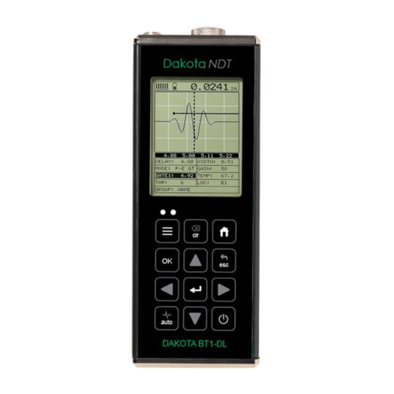
- Page 11 P. Detect/Gate/Threshold – The broken dotted line demonstrates where the BT1-DL is currently detecting on the waveform. Notice the horizontal line with an arrow pointing at the detection point. This is the ‘gate’, and the height of...
-
Page 12: Tabbed & Hot Menu Reference
The BT1-DL has 11 tabbed menu titles and multiple submenu items as illustrated below. The BT1-DL also has 1 ‘hot menu’... - Page 13 BT1-DL Bolt Tension Monitor >> End DATA UTILS XFER PROJECT TEMP UPGRADE MODE GAUGE ALARM CAPTURE TO FILE EDIT ALARM CAPTURE VIEWER OPEN ALARM ABOUT HIGH CLOSE KEY CLICK DELETE SET DATE ONE FILE DELETE SHOW ALL DATA DATE SUMMARY...
-
Page 14: Chapter Three Quick Start Guide
1) Remove the BT1-DL from the carrying case. 2) Connect the transducer cable to the transducer and plug it into the BT1-DL. 3) If a temperature sensor is being used, connect the sensor to the BT1-DL. 3.3 Setting up the BT1-DL Please Read: In this section the BT1-DL will be setup in its simplest form. - Page 15 BT1-DL Bolt Tension Monitor 1) Press the key to power up the BT1-DL. 2) Press the key once to activate the menu items tab. Press the multiple times to tab right and the key multiple times to tab left until the SETUP menu is highlighted and displaying the submenu items.
- Page 16 Dakota NDT Note: The default setup, selected in the previous section, automatically defaults to English units – inches. Follow the procedure below to change the units to Metric, if needed. 1) Press the key multiple times to tab right and the key multiple times to tab left until the MATL menu is highlighted and displaying the submenu items.
-
Page 17: Creating A New Group To Store Measurements
3.4 Creating a New Group to Store Measurements Now that the BT1-DL is all setup, this section will explain how to get started measuring unloaded initial lengths. In order to do this, we need to create a group that contains bolts. - Page 18 Dakota NDT 1) Press the key once to activate the menu items tab. Press the multiple times to tab right, and the key multiple times to tab left, until the DATA menu is highlighted and displaying the submenu items. 2) Press the arrow keys multiple times to scroll through the sub menu items until NEW is highlighted.
- Page 19 BT1-DL Bolt Tension Monitor 8) Use the key to backspace if necessary. 9) Repeat steps 6 - 8 until the Group Name is completed. 10) Press the key to save the Group Name and return to the Group List Items menu, or to cancel entering the Group Name.
- Page 20 Dakota NDT 4) Press the key to select a character and advance to the next field of the Group Note. 5) Use the key to backspace if necessary. 6) Repeat steps 3 - 5 until the Group Note is completed. 7) Press the key to save the Group Note and return to the Group List Items menu, or...
- Page 21 BT1-DL Bolt Tension Monitor 5) Repeat steps 3 & 4 until the NUM BOLTS value is correctly displayed. 6) Press the key to save the NUM BOLTS and return to the Group List Items menu, or to cancel entering the NUM BOLTS.
- Page 22 “NOT ENOUGH MEMORY” will be displayed. Press the to return to the Group List Items menu. It may be necessary to free some memory in the BT1-DL at this time. Selecting the Starting Bolt Number Note: Depending on the application and layout of the project, the user won’t always want the starting bolt to be 1.
- Page 23 BT1-DL Bolt Tension Monitor 1) Press the arrow keys multiple times to scroll through the new Group List Items until START BOLT NUM is highlighted. 2) Press the key to display the Digits Edit Box. 3) Press the arrow keys multiple times to scroll the highlighted value.
- Page 24 Dakota NDT Selecting the Auto Increment Direction The Auto Increment feature gives the user the ability to specify which direction to advance the cursor after storing a reading. 1) Press the arrow keys multiple times to scroll through the new Group List Items until INCR.
-
Page 25: Setting The Approximate Length
In order to utilize the AUTO SET feature of the BT1-DL, when measuring reference lengths, the BT1-DL has to know where to start looking for the detection. We can accomplish this by entering an approximate length into the gauge. The BT1-DL will automatically take the value entered and scan +/- 5% in both directions of the approximate length for the detection signal. - Page 26 Dakota NDT 1) Press the key once to activate measure menu items. Press the key multiple times to advance to the next cell right and the key multiple times to advance to the next cell left, until the ALEN cell is highlighted. 2) Press the key to display the Digits Edit Box.
- Page 27 BT1-DL Bolt Tension Monitor 1) Press the key once to activate the menu items tab. Press the multiple times to tab right, and the key multiple times to tab left, until the AUTO menu is highlighted and displaying the submenu items.
-
Page 28: Measuring Reference Lengths
Dakota NDT 3.6 Measuring Reference Lengths At this point, the BT1-DL is setup and ready to start measuring reference lengths. We’ve already setup a bolt group to store the reference length data, and now need to display the group storage locations prior to making measurements. -
Page 29: Measuring Elongations
BT1-DL Bolt Tension Monitor moving the transducer to a completely different location on the bolt, thus causing potentially erroneous measurements. Be consistent and as methodical in your methods as possible. This will help to avoid transducer placement errors. 5) Press the key, located in the bottom left corner of the keypad, to locate the detection point, or end of the bolt. - Page 30 Dakota NDT 1) Press the arrow keys to scroll the target cell cursor to the desired storage location. Note: Elongation values must be stored in column B - ZZ. Note: Do not press the key, while measuring elongation’s, as this activates a high speed mode used specifically with our shut-off box.
-
Page 31: Chapter Four Keyboard, Menu, & Connector Reference
CHAPTER FOUR KEYBOARD, MENU, & CONNECTOR REFERENCE 4.1 Menu Key (Operation & Sub Menus) The MENU key activates the primary menu structure containing 11 menu tab groups. These tab groups then contain sub menu items, or functions. The sub menu items have been organized in tab groups according to how closely they are related to the individual tab group names. - Page 32 Dakota NDT Activating and Getting Around in the Menu Items 1) Press the key once to activate the menu items tab. Press the multiple times to tab right, and the key multiple times to tab left until the desired tab group is highlighted and displaying the submenu items (A). Now that you’re familiar with activating and moving amongst the tab groups, let’s have a look at how to move around in the sub menu items as follows: Getting Around in the Sub Menu Items...
-
Page 33: Cal - Menu
BT1-DL Bolt Tension Monitor 4.2 CAL – Menu ZERO MODE: The BT1-DL is zeroed in much the same way that a mechanical micrometer is zeroed. There are three zero mode options available in the BT1-DL – FIXED, ONE POINT, TWO POINT and AUTO. Selecting the proper mode is dependent on the application requirements, but the most convenient mode of preference is - AUTO. -
Page 34: Matl (Material) - Menu
Dakota NDT 4.3 MATL (material) – Menu UNITS: Toggle between English and Metric units and multiple resolutions for each unit ( IN - .0001, INHR - .00001, or MM - .001, MMHR - .0001 ), Using the abbreviation HR to represent High Resolution. TYPE: Select the bolt material type from a preset list of material types. -
Page 35: Disp (Display) - Menu
BT1-DL Bolt Tension Monitor vector using the BT1-DL or utility software. Alternatively, the load factor can be determined using the bolt calculator in the utility software. However, if extreme accuracy is required, performing a field calibration is a must. This sub menu item enables the user to edit the factor at anytime. -
Page 36: Tune - Menu
The pulse width refers to the duration of time the pulser is on. There are three different types of pulsers built into the BT1-DL – Spike, Square Wave, and Tone Burst with adjustable voltage options of 100-400 volts and select settings of Spike, Thin, Wide, HV Spike, HV Thin, HV Wide, TB 10MHz, TB 5MHz, TB 2MHz, and TB 1MHz. -
Page 37: Gates - Menu
APPROX LEN: In order for the user to use the Auto Set feature, an approximate length of the fastener must be entered. The approximate length gives the BT1-DL some idea of where to turn on the receiver and look for the detection, or end of the bolt. -
Page 38: Setup - Menu
Refer to page 164 for further info. DEFAULT SETUP: Loads a basic default setup. Use only as a last resort when the setups in the BT1-DL have been corrupted and a computer is not accessible. Refer to page 166 for further info. -
Page 39: Util (Utilities) - Menu
(manual, semi-auto, and auto). This feature is only available to those units purchased with the automatic temperature compensation option and probe. Note: Contact Dakota for information on upgrading the BT1-DL. Refer to page 67 for further info. -
Page 40: Xfer (Transfer) - Menu
The primary function of the OK key is confirmation of a change or selection. The OK key also toggles between full or split screen view while in the main measurement screen. If the BT1-DL is displaying a data group, the OK key toggles an advance to row number option. -
Page 41: Esc Key
The AUTO SET is an automatic measurement routine that attempts to locate the detection and set all the scope parameters of the BT1-DL. Additionally, “capture to file” allows the user to take a snapshot of the current screen, give it a name, and save it to the SD card. - Page 42 Dakota NDT The diagram above is a screenshot of the “Hot Menu” in the BT1-DL. The Hot Menu contain all the most regularly adjusted features. The primary purpose of the design was to provide the user with an efficient way to make adjustments on the fly, while continuing to have visibility of the A-Scan display.
-
Page 43: Top & Bottom End Caps
4.22 Top & Bottom End Caps The top & bottom end panels are where all connections are made to the BT1-DL. The diagram above shows the layout and description of the connectors: Transducer Connector Refer to Diagram: The transducer connector is a board mounted and shielded LEMO “00”. -
Page 44: Chapter Five Theory Of Operation
The digital signal processor optimizes the measurement process. 5.2 Features of the BT1-DL The Dakota NDT BT1-DL, Ultrasonic Bolt Tension Monitor, defines the State of the Art in the measurement of the actual clamp load produced by tightening a fastener. -
Page 45: Ultrasonic Waves
5.4 Measurement Mode The BT1-DL uses a standard pulse-echo (P-E) mode for measurement. This is accomplished by measuring from the initial pulse (sometimes referred to as and artificial zero) to the first echo (reflection). In this mode errors can result from surface coatings applied to the bolt, as well as temperature variations. -
Page 46: Chapter Six Bolt Preparation
6.1 Use of Ultrasonic Couplant Sonic energy at the frequency range used by the BT1-DL travels well through solid materials and most liquids. It does not travel well through air. This variable resistance to the passage of sonic energy is called sonic impedance. - Page 47 BT1-DL Bolt Tension Monitor Figure 1 Sound path in a good bolt Smooth, even surfaced bolt ends that seat the entire active surface of the transducer with minimum gap are required for accurate signal transmission. Bolt ends may need to be cleaned, ground, etc. to achieve the required surface.
-
Page 48: Bolt End Reflectors
Dakota NDT Figure 3 Effect of lowered and raised grade marks 6.3 Bolt End Reflectors Smooth, flat reflecting bolt ends that are perpendicular to the axis of the bolt are required for accurate echo reception. Bolt ends may need to be cleaned, ground, etc. to achieve the required surface. - Page 49 BT1-DL Bolt Tension Monitor Figure 6 Reflection in a bending bolt...
-
Page 50: Chapter Seven Transducer Selection
CHAPTER SEVEN TRANSDUCER SELECTION 7.1 Selecting the Transducer Transducer selection is a very import part of getting the best results from the BT1- DL. The frequency and diameter of transducer should be carefully selected using the following information: Select the largest diameter transducer that will seat completely on the end of the bolt. -
Page 51: Chapter Eight Measuring System Zero (Calibration)
In this chapter will be focused on establishing a system zero to enable the group data to be portable between different hardware devices with limited measuring error. Data created using one BT1-DL, can send the data file to another operator for use in another BT1-DL, transducer (diameter or frequency), or cable (length or type). The BT1-DL offers a few selectable calibration options for flexibility based on preference, or the type of calibration standard used. -
Page 52: Creating A Group To Document Zero (Calibration) Data
Dakota NDT instrument. Check in with your quality department to verify their duration requirement for “Test & Measurement Equipment”. 8.3 Creating a Group to Document Zero (Calibration) data A project folder named “CAL_ZERO_DATA” will automatically be created following the completion of a “One Point”, “Two Point”, or “Auto” calibration option…if one doesn’t already exist. -
Page 53: Auto - Zero/Calibration
(not recommended for use with our triple path glass block). If valid signals cannot be acquired during the ‘auto set’ routine, the BT1-DL will report “can’t find stable echo”. Before eliminating this option altogether and using one of the manual options listed below, try relocating the transducer to various positions on the end of the calibration standard first. - Page 54 Dakota NDT 1) Press the key multiple times to tab right and the key multiple times to tab left until the CAL menu is highlighted and displaying the submenu items. 2) Press the arrow keys multiple times to scroll through the sub menu items until ZERO MODE is highlighted.
- Page 55 Note: The BT1-DL will automatically begin the wave analysis for each measurement, display a summary page of the fit, calculated velocity, zero values, and return to the main measurement screen when completed.
-
Page 56: One & Two Point Zero Calibration
BT1-DL. To reiterate, a data group will automatically be created following the completion of either of these two zero calibration methods. For additional information on the group data file refer to section 8.3. - Page 57 BT1-DL Bolt Tension Monitor The zero calibration procedure is as follows: One & Two Point System Zero 1) Press the key multiple times to tab right and the key multiple times to tab left until the CAL menu is highlighted and displaying the submenu items.
- Page 58 Dakota NDT 4) Press the arrow keys multiple times to scroll through the sub menu items until MEASURE ZERO is highlighted. 5) Press the key to display the Zero Calibration menu items. 6) Press the arrow keys multiple times to scroll through the sub menu items until PHY LEN 1 is highlighted.
- Page 59 BT1-DL Bolt Tension Monitor 10) Repeat steps 6 – 9, if using the TWO POINT zero calibration method, to enter and save PHY LEN 2. 11) Press the arrow keys multiple times to scroll through the sub menu items until VELOCITY is highlighted.
- Page 60 Dakota NDT 14) Press the arrow keys multiple times to scroll through the sub menu items until TEMP COEF is highlighted. 15) Press the key to display the Digits Edit Box and adjust the TEMP COEF. Note: The Temperature Coefficient (Temp Coef) should be set to ’55’ when using the 3”...
- Page 61 BT1-DL Bolt Tension Monitor 18) Press the arrow keys multiple times to scroll through the sub menu items until POLARITY is highlighted. 19) Press the arrow keys multiple times to scroll the POLARITY options (auto, positive, negative) until the desired option is displayed.
- Page 62 Dakota NDT 21) Press the arrow keys multiple times using the left button wheel to scroll through the sub menu items until ULTRASONIC 1 is highlighted. 22) Press the key to start the automated zero calibration routine. Note: A waveform will be displayed with “CALC ZERO”, noted in the top right corner of the display.
- Page 63 BT1-DL Bolt Tension Monitor 26) Press the key to calculate the zero and display the PROBE DIAMETER list box. The diameter should be noted on the transducer housing. 27) Press the arrow keys multiple times to scroll the probe diameter options.
-
Page 64: Verification Of System Zero Calibration
Dakota NDT Note: The system zero calibration routine just performed is entirely independent of the bolt measurement section. Therefore, be sure the MAX II is setup for the actual bolts intended prior to measurement. 8.6 Verification of System Zero Calibration The system zero can be verified either immediately following completion of one of the zero calibration methods described in the previous sections, prior to starting a new/existing job, or because the hardware has been changed in some way (gauge,... - Page 65 BT1-DL Bolt Tension Monitor 2) Press the arrow keys multiple times to scroll through the sub menu items until VELOCITY is highlighted. 3) Press the key to display the Digits Edit Box and adjust the VELOCITY to the Zero Calibration velocity calculated.
- Page 66 Dakota NDT 8) Press the key to display the Digits Edit Box and adjust the APPROX LEN for 2” to find the correct length. 9) Press the arrow keys multiple times to scroll the highlighted value until the desired APPROX LEN is correctly displayed. 10) Press the key to save the APPROX LEN and display the AUTO menu items.
- Page 67 BT1-DL Bolt Tension Monitor 1) Press the key multiple times to tab right and the key multiple times to tab left until the DATA menu is highlighted and displaying the sub menu items. 2) Press the arrow keys multiple times to scroll through the sub menu items until PROJECT is highlighted.
- Page 68 Dakota NDT 5) Press the key to display the Confirmation screen, followed by pressing key to change the project folder. 6) Press the arrow keys multiple times to scroll through the menu items until OPEN is highlighted. 7) Press the key to display the Cal Zero group data files in the project.
- Page 69 BT1-DL Bolt Tension Monitor CALZERO220329_090431 Date(yr/month/day)_Time(hr/min/sec) 8) Press the arrow keys multiple times to scroll through the log files until the appropriate log file is highlighted. 9) Press the key to display the highlighted CALZERO group log file. 10) Press the arrow keys multiple times using the left button wheel to scroll the cursor to an empty elongation column B–K on row #2 to...
- Page 70 2” side and attach the transducer to the Glass Block. 2) Press the key to find the 2” echo and optimize the BT1-DL setup. Note: Review the waveform and length displayed for a tolerance 0.0005”. Rotate, maneuver, and vary pressure on the transducer, while searching for a length that’s inside of allowable tolerance.
-
Page 71: Using A 'Set Aside' Bolt
The primary objective is to establish a zero, verify a zero value prior to measuring, and avoid measurement errors if the BT1-DL, transducer, or cable has been replaced. While this sounds like an economic way to go, the operator... - Page 72 Dakota NDT 4) Press the arrow keys multiple times using the left button wheel to scroll through the material list until the appropriate material is highlighted. 5) Press the key to display the confirmation screen. 6) Press the key to select the material and return to the menu screen, or ESC to cancel the material selection.
-
Page 73: Chapter Nine Temperature Compensation
CHAPTER NINE TEMPERATURE COMPENSATION 9.1 Purpose The temperature of a fastener affects the overall physical length, as well as the velocity of a fastener. As the temperature of a fastener increases, the ultrasonic length increases at a rate greater than the physical change in length. If the user intends to measure the same fastener at different time intervals over the service life of the bolt, temperature compensation is very important to produce accurate results. -
Page 74: Semi Automatic Mode
Dakota NDT 2) Press the arrow keys multiple times to scroll through the sub menu items until TEMP MODE is highlighted. 3) Press the arrow keys multiple times to scroll the temperature mode options. Once the MANUAL temperature mode is displayed, press key to return to the measurement screen. - Page 75 BT1-DL Bolt Tension Monitor automatically changing. Some companies and application procedures may call for manually initiating and physically viewing the change in temperature by adding a manual step to the procedures. The semi automatic mode answers requirements such as these.
-
Page 76: Automatic Mode
9.4 Automatic Mode The automatic mode constantly monitors and compensates for temperature when the accessory temperature sensor is attached to the BT1-DL and placed on the joint or fastener being measured. While this mode eliminates the need to manually insert or... -
Page 77: Chapter Ten Bolt Material Calibration
BOLT MATERIAL CALIBRATION 10.1 Why Calibrate? The preset bolt types in the BT1-DL contain average factors for the material type. These are approximate values only. In a tightly controlled application where extreme accuracy is required, it is necessary to obtain all the information possible about the fasteners being measured. - Page 78 Dakota NDT 3) Press the arrow keys multiple times to scroll the quantity until ELONG is displayed. 4) Press the key multiple times to tab right, and the key multiple times to tab left, until the MATL menu is highlighted and displaying the submenu items.
- Page 79 BT1-DL Bolt Tension Monitor 10) Press the key multiple times to tab right, and the key multiple times to tab left, until the AUTO menu is highlighted and displaying the submenu items. 11) Press the arrow keys multiple times to scroll through the sub menu items until APPROX LEN is highlighted.
- Page 80 Dakota NDT 18) Apply a drop of couplant to the bolt or transducer, and attach it to one end of the bolt. Rotate the transducer clockwise and counter clockwise applying a small amount of pressure to eliminate any excess couplant between the transducer and bolt surface.
-
Page 81: Stress Factor Calibration
BT1-DL Bolt Tension Monitor 22) Press the arrow keys multiple times to scroll through the sub menu items until VELOCITY is highlighted. 23) Press the key to display the Digits Edit Box. Note: Enter the Correct Velocity calculated above. 24) Press the arrow keys multiple times to scroll the highlighted value. - Page 82 Sonic Stress Factor is to be determined. NOTES: The Dakota NDT BT1-DL must be calibrated, or zeroed, as described in the Zero Calibration procedure section 8.5. The Velocity Calibration should be performed prior to determining the Stress Factor.
- Page 83 Note: The following steps assume that the user has performed the steps in the previous section and calibrated the velocity. Therefore, the velocity has been adjusted, approximate length already entered, and the BT1-DL is currently setup and ready to measure in elongation mode.
- Page 84 Dakota NDT working conditions. Using the mechanical measuring device, measure and record the Mechanical Length at Load 1 “ L ” for the current sample bolt. 6) Apply a drop of couplant to the bolt or transducer, and attach it to one end of the bolt.
-
Page 85: Temperature Factor Calibration
The BT1-DL always measures a fastener at 68 F. If the temperature of the fastener is currently being measured at 108 F, the BT1- DL will compensate, or correct, the measurement back to 68 ... - Page 86 Temperature Factor is to be determined. NOTES: The Dakota NDT BT1-DL must be calibrated, or zeroed, as described in the procedure entitled Measuring System Zero in 8.1. The sample bolts should be left to soak at the measured temperature points for a period of not less than 20 minutes, to insure that temperature is uniform throughout the sample.
- Page 87 BT1-DL Bolt Tension Monitor transducer and bolt. Be sure to always place the transducer in the same location. This will help to eliminate any potential measurement errors caused by changing the sound path. 3) Record the ultrasonic length “L ” of the sample bolt at the above minimum...
-
Page 88: Chapter Eleven Load Measurment
The cross sectional area of the bolt is defined as the average area of a fastener under stress. This factor is only used in the BT1-DL’s calculation of load. It has no effect on stress or elongation, time, or strain, and is directly proportional to the load measured ultrasonically. - Page 89 BT1-DL Bolt Tension Monitor For bolts with complex geometry, the areas should be estimated by averaging each individual area and length. In the case of a hollow fastener, the area of the hole must be subtracted from the overall area. The area of a fastener with complex geometry can be estimated as follows: ...
-
Page 90: Calibrating Load Factor (Field Calibration)
A field calibration is accomplished using a tensile tester, load cell, or other calibrated load device to compare known loads against ultrasonic elongations. The BT1-DL is equipped with a self- calibrating feature that uses a linear regression or vector equation to produce a best-fit line through the known loads, minimizing error. -
Page 91: Performing A Field Calibration
BT1-DL Bolt Tension Monitor zero and produces only a load factor. Why are both options needed? In applications where a small amount of load is applied to the fastener, thus producing very little elongation, the regression option can potentially produce non-linear results. In cases such as these, a vector may sometimes produce better results as the offset is set at zero. - Page 92 Dakota NDT Note: Select a name that references this group to Field Calibration Data. 1) Press the key once to activate the menu items tab. Press the multiple times to tab right, and the key multiple times to tab left, until the DATA menu is highlighted and displaying the submenu items.
- Page 93 BT1-DL Bolt Tension Monitor 6) Press the arrow keys to scroll to highlight the appropriate alpha characters. 7) Press the key to select a character and advance to the next field of the Group Name. 8) Use the key to backspace if necessary.
- Page 94 Dakota NDT 1) Press the arrow keys multiple times to scroll through the new Group List Items until NOTE is highlighted. 2) Press the key to activate the Alpha Edit Box. 3) Press the arrow keys to scroll to highlight the appropriate alpha characters.
- Page 95 BT1-DL Bolt Tension Monitor 1) Press the arrow keys multiple times to scroll through the new Group List Items until NUM BOLTS is highlighted. 2) Press the key to display the Digits Edit Box. 3) Press the arrow keys multiple times to scroll the highlighted value.
- Page 96 If there’s not enough memory available to create the group, an error message box “NOT ENOUGH MEMORY“ will be displayed. Press the to return to the Group List Items menu. It may be necessary to free some memory in the BT1-DL at this time.
- Page 97 BT1-DL Bolt Tension Monitor Selecting the Starting Bolt Number Note: Depending on the application and layout of the project, the user won’t always want the starting bolt to be 1. This feature allows the user to define what the starting number will be.
- Page 98 Dakota NDT Note: If a value is enter that is greater than the maximum number of bolts allowed per group (250), an error message box “VALUE IS OUT OF RANGE” will be displayed. 7) Press the key to display the Digits Edit Box and re-enter the START BOLT NUM.
- Page 99 BT1-DL Bolt Tension Monitor Saving the Group Once all the parameters are set, the user has the option of saving or canceling the new group. 1) Press the arrow keys multiple times to scroll through the new Group List Items until CREATE NEW GROUP? is highlighted.
- Page 100 Dakota NDT Storing the Reference Length 1) Press the key once to activate measure menu items. Press the key multiple times to move right and the key multiple times to move left until the LOG cell is highlighted. 2) Press the key to display the Group View Box.
- Page 101 Note: The following steps assume that the user has previously selected a similar material type for the list of materials and the approximate length of the bolt has been entered. Therefore, the BT1-DL is currently setup and ready to measure in elongation mode.
- Page 102 Dakota NDT 4) Apply approximately 1/3 of the maximum load, which is to be placed on the bolt under actual working conditions. 5) Measure and record the Ultrasonic Length at Load 1 by pressing the key. The Digits Edit Box will be displayed. Note: Load 1 should be stored in column B.
- Page 103 BT1-DL Bolt Tension Monitor 15) Press the key to store the Known Load and return to the measurement screen, or to cancel entering the Known Load. 16) Increase the applied load to approximately the maximum load, which is to be placed on the bolt under actual working conditions.
- Page 104 Dakota NDT 2) Press the arrow keys multiple times to scroll through the sub menu items until LOAD CAL CALC is highlighted. 3) Press the key to run the calculation and display the confirmation screen. Note: The regression or vector coefficient will be displayed. The closer this number is to 1, the better the fit, or least amount of error.
-
Page 105: Chapter Twelve Measurement & Waveform Display
MEASUREMENT & WAVEFORM DISPLAY 12.1 Quantities of Measurement The BT1-DL has the ability to measure in a number of measurement quantities: Time (nanoseconds), Elongation, Load, Stress, and Strain (in terms of %). While there are a number of quantity options available, the easiest and most fail safe quantities to consider are Time and Elongation. -
Page 106: Display View Options
Dakota NDT 12.2 Display View Options A key feature of the BT1-DL is the versatility of the display views available to the user. The waveform views are a graphical representation of the actual sound reflections traveling through a fastener and returning back to the transducer. The waveform display shows the amplitude of the signal received on the vertical (Y) axis and time (displayed in terms of length) on the horizontal (X) axis. - Page 107 BT1-DL Bolt Tension Monitor Digits Hot Menus RF Hot Menus Changing Display Options 1) Press the key once to activate the menu items tab. Press the multiple times to tab right, and the key multiple times to tab left, until the DISP menu is highlighted and displaying the submenu items.
- Page 108 When all the vertical bars are fully illuminated and the last digit on the digital thickness value is stable, the BT1-DL is reliably measuring the same value on a consistent basis. B. Battery Icon – Indicates the amount of battery life the BT1-DL has remaining.
- Page 109 P. Detect/Gate/Threshold – The broken dotted line demonstrates where the BT1-DL is currently detecting on the waveform. Notice the horizontal line with an arrow pointing at the detection point. This is the ‘gate’, and the height of...
-
Page 110: Adjusting The Display
Dakota NDT 12.3 Adjusting the Display The width refers to the overall viewable range, with respect to length, being displayed on the screen. The starting length is displayed at the lower left side of the screen, and the ending length is shown at the lower right hand side of the screen. The difference between these values is called the Width. - Page 111 BT1-DL Bolt Tension Monitor Adjusting the Width using the Tabbed Menus 1) Press the key once to activate the menu items tab. Press the multiple times to tab right, and the key multiple times to tab left, until the DISP menu is highlighted and displaying the submenu items.
- Page 112 Dakota NDT Starting delay The starting DELAY, or starting length, is the value displayed on the bottom lower left side of the display in both RF and RECT (Rectified) views. Note: Once the range is set, it will remain the same for all the views respectively. The procedures to adjust the Delay are outlined below: Adjusting the Delay using the Hot Menus 1) Press the...
- Page 113 BT1-DL Bolt Tension Monitor 1) Press the key once to activate the menu items tab. Press the multiple times to tab right, and the key multiple times to tab left, until the DISP menu is highlighted and displaying the submenu items.
-
Page 114: Gain
Dakota NDT 12.4 Gain The gain, or amplification of the return echoes, can be adjusted over a wide range. The setting of the gain is crucial in order to obtain valid readings during the measurement process. Too much gain may result in erroneous measurements, by detecting on noise rather than the length of the fastener itself. - Page 115 BT1-DL Bolt Tension Monitor The user can also access and adjust the gain from the tabbed menus. However, this method is more tedious than making the adjustments using the hot menu. The procedure using the tabbed menus is outlined below:...
- Page 116 Dakota NDT 5) Press the arrow keys multiple times to scroll the highlighted value. 6) Press the arrow keys multiple times to scroll the digit locations. 7) Repeat steps 5 & 6 until the GAIN value is correctly displayed. 8) Press the key to set the GAIN and return to the menu screen, or to cancel entering the GAIN.
-
Page 117: Gate
12.5 Gate The BT1-DL is equipped with a single gate typically used to block or eliminate noise that is present prior to the reflection from the end of the bolt, and also to force a detection at or on a specific location or waveform. In some cases the first reflection from the end of the bolt will not produce a suitable symmetrical waveform. - Page 118 Another potential issue is general transducer or low frequency noise. In this type of situation, the noise interferes with the BT1-DL and has enough amplitude to cause the BT1-DL to detect on the noise rather than the true return reflection. The diagram below illustrates both cases: Gate The horizontal line at the top of (D) represents the GATE.
- Page 119 BT1-DL Bolt Tension Monitor 1) Press the key once to activate measure menu items. Press the key multiple times to move right and the key multiple times to move left until the GATE cell is highlighted. 2) Press the arrow keys multiple times to scroll the highlighted value.
-
Page 120: Threshold
Dakota NDT 1) Press the key once to activate the menu items tab. Press the multiple times to tab right and the key multiple times to tab left until the AUTO menu is highlighted and displaying the submenu items. 2) Press the arrow keys multiple times to scroll through the sub menu items until GATE is highlighted. - Page 121 BT1-DL Bolt Tension Monitor The procedures to adjust the Thresholds are outlined below: Adjusting the Thresholds using the Hot Menus 1) Press the key once to activate measure menu items. Press the key multiple times to move right and the key multiple times to move left, until the desired Threshold cell is highlighted.
- Page 122 Dakota NDT 1) Press the key once to activate the menu items tab. Press the multiple times to tab right, and the key multiple times to tab left, until the GATES menu is highlighted and displaying the submenu items. 2) Press the arrow keys multiple times to scroll through the sub menu items until Threshold is highlighted.
-
Page 123: Interpreting The Waveform
When this occurs, the decrease in amplitude can cause the BT1-DL to lose the first cycle altogether. If the first cycle is lost, the BT1-DL will “peak Jump” to another cycle later in time with greater amplitude. Often times transducers have a very slow ramp up time until reaching maximum energy. -
Page 124: Manually Locating The Echo
The echo can be manually located by simply adjusting the delay and width values of the BT1-DL. While this is process is very tedious and will most often not be used because of the Auto Set feature, it should be explained for general control of the instrument. - Page 125 BT1-DL Bolt Tension Monitor 1) Press the key once to activate measure menu items. Press the key multiple times to move right and the key multiple times to move left, until the DELAY cell is highlighted. 2) Press the arrow keys multiple times to scroll the highlighted value.
-
Page 126: Automatic Echo Optimization (Auto Set)
BT1-DL. The approximate length tells the BT1- DL where to start looking for the echo. The BT1-DL will search +/- 5% from the value entered. The following procedures outline the Auto Set feature. - Page 127 BT1-DL Bolt Tension Monitor 1) Press the key once to activate measure menu items. Press the key multiple times to move right and the key multiple times to move left, until the ALEN cell is highlighted. 2) Press the key to display the Digits Edit Box.
- Page 128 Approx. Len. Using Auto Set Note: If the Approximate length has been entered into the BT1-DL, the Auto Set feature can be run simply by pressing the AUTO SET key at the bottom left of the keypad.
-
Page 129: Unloaded Length And Elongation Measurements
BT1-DL Bolt Tension Monitor 1) Press the key once to activate the menu items tab. Press the multiple times to tab right, and the key multiple times to tab left, until the UTIL menu is highlighted and displaying the submenu items. -
Page 130: Chapter Thirteen Additional Features
ADDITIONAL FEATURES 13.1 Quality/Correlation (Transducer Placement) The auto correlation feature in the BT1-DL is a handy feature to assist the user with returning the transducer back to the original position/location where it was during the initial reference length measurement. Since the sound path is changing, in terms of material consistency, returning the transducer to the same location increases the accuracy of the BT1-DL, reducing what is referred to as the “placement error”. -
Page 131: Contrast
Note: When a custom setup file is recalled and opened, the following warning screen will be displayed. 13.3 Contrast The BT1-DL is equipped with a contrast feature to adjust the display visibility in different light conditions. It has an arbitrary scale with a values from 1-20, with 20... -
Page 132: Backlight
13.4 Backlight The BT1-DL has an EL backlit display with the setting options: off, on, auto, invert (inverted) to for various light conditions. The procedure for enabling the Backlight is as follows:... -
Page 133: Graphics Options (Look & Feel)
13.5 Graphics Options (look & feel) The BT1-DL has a few graphical ‘look and feel’ options to accommodate user preference. These features only serve as cosmetic items and do not change the functionality of the BT1-DL in any way. - Page 134 Dakota NDT Filled – Draws a filled version of the waveform. Detect Mark: The detect mark is another look and feel option for displaying the detection indicator.
-
Page 135: Pulse
BT1-DL Bolt Tension Monitor 13.6 Pulse The BT1-DL has a 200 volt square wave pulser. Pulse width, refers to the duration of time the pulser is left on. This time results in increased energy sent into the fastener. There are three pulse width options (SPIKE, THIN, and WIDE), with adjustable pulser voltages of 100, 150 and 200 volts. -
Page 136: Pulser Voltage
13.7 Pulser Voltage The BT1-DL has a 200 volt square wave pulser that can be adjusted for specific bolt lengths, geometries, materials, transducer size and frequencies. The Pulser Voltage feature offers various voltage settings of 100, 150 & 200 volts. Lower voltage selections are best for short small diameter bolts, while higher voltage are best for longer bolts with attenuative or inconsistent materials. -
Page 137: Damping
13.8 Damping The BT1-DL has a built-in damping feature to control the impedance input of the receiver. This enables the user the ability to match and optimize the transducer for better signal quality at various frequencies. The available settings are 50, 75, 100, 300, 600 and 1500 ohms. -
Page 138: Digitizer
Dakota NDT 1) Press the key once to activate the menu items tab. Press the multiple times to tab right, and the key multiple times to tab left, until the TUNE menu is highlighted and displaying the submenu items. 2) Use the arrow keys multiple times to scroll through the sub menu items until DAMPING is highlighted. -
Page 139: Polarity
Refer to section 12.7, interpreting the Waveform, for a detailed explanation on how to select the proper polarity. It’s also important to note that the BT1-DL auto set feature will automatically select and set the polarity, but it’s important to review, understand, and check that BT1-DL selected the proper polarity. -
Page 140: Alarm Mode
There are two limits, or alarm values, that can be setup in the BT1-DL – ALARM LOW and ALARM HIGH limits. However, the user may choose to activate and utilize... - Page 141 BT1-DL Bolt Tension Monitor Note: The alarm feature can also be used in conjunction with an accessory high speed shutoff box that is wired into the power of the pump and will shutdown the pump when inside of the alarm limit values.
- Page 142 Dakota NDT 1) Assuming the ALARM is ON, press the arrow keys multiple times to scroll through the sub menu items until ALARM LOW is highlighted. 2) Press the key to display the Digits Edit Box. 3) Press the arrow keys multiple times to scroll the highlighted value.
-
Page 143: Key Click
BT1-DL Bolt Tension Monitor 13.12 Key Click When a key is pressed on the BT1-DL keypad, the user can control whether or not an audible beep is sounded and at what volume level, if any. The procedure for this feature/preference is outlined below:... - Page 144 Dakota NDT 1) Press the key once to activate the menu items tab. Press the multiple times to tab right and the key multiple times to tab left until the UTIL menu is highlighted and displaying the submenu items. 2) Use the arrow keys multiple times to scroll through the sub menu items until SET DATE is highlighted.
-
Page 145: Upgrade Gauge
13.14 Upgrade Gauge The BT1-DL can be upgraded very conveniently at your desk or in the field. The latest version of firmware can be found on the Dakota website, which can be compared to the current version loaded in the BT1-DL. The version is displayed to the right of the ABOUT menu item in the XFER menu. -
Page 146: Freeze & Capture
Each snapshot can be individually named and stored as a .tif (tagged image) file. This can be opened using any graphics viewer. With the storage capacity of the BT1-DL at 4GB, the user can store as many screens shots as needed. -
Page 147: Capture Viewer
The capture viewer enables a user to view any of the saved screen captures on the SD card, using the BT1-DL. This is handy if a PC isn’t available, but the user has a need to review the screen shots captured. - Page 148 Dakota NDT 1) Press the key once to activate the menu items tab. Press the multiple times to tab right and the key multiple times to tab left until the XFER menu is highlighted and displaying the submenu items. 2) Press the arrow keys until CAPTURE VIEWER is highlighted.
-
Page 149: Chapter Fourteen Data Storage - Setup, Edit, & View Files
The BT1-DL always contains one “default” project that can contain as many groups as needed. In other words, if a project was never created, the BT1-DL will automatically continue to store all data groups in the “default” project folder. - Page 150 Dakota NDT 2) Press the arrow keys until NEW is highlighted. 3) Press the key to display the new Group List Items. 4) Use the arrow keys to scroll through the list until PROJECT is highlighted. 5) Press the key to activate the Alpha Edit Box. 6) Press the arrow keys to scroll to the appropriate alpha characters.
-
Page 151: Viewing & Opening A Project Folder
BT1-DL Bolt Tension Monitor Note: New project folders can additionally be created using a PC. Simply connect the BT1-DL to the PC, navigate to the USB drive, or SD card and create new folders. 14.3 Viewing & Opening a Project Folder... -
Page 152: Introduction To Group (Spreadsheet) Format
14.4 Introduction to Group (spreadsheet) format Data is stored in the BT1-DL in a spreadsheet like format called a GRID. A GRID is simply a table of readings. In the case of the BT1-DL they will be discussed in terms of a GROUP. -
Page 153: Creating A New Group
BT1-DL Bolt Tension Monitor The BT1-DL can store a great deal of data, considering there is a 4 GB internal SD card on the board, as well as an external SD slot that will accept up to 64 GB cards. - Page 154 Dakota NDT 1) Press the key once to activate the menu items tab. Press the multiple times to tab right, and the key multiple times to tab left, until the DATA menu is highlighted and displaying the submenu items. 2) Use the arrow keys multiple times to scroll through the sub menu items until NEW is highlighted.
- Page 155 BT1-DL Bolt Tension Monitor 6) Press the arrow keys to highlight the appropriate alpha/numeric characters. 7) Press the key to select a character and advance to the next field. Note: Use the key to backspace if necessary. 8) Repeat steps 6 - 7 until the NAME, NOTE, NUM. BOLTS, NUM. READS, START BOLT, or INCR DIR is completed.
-
Page 156: Storing A Reading
This section assumes the group was just created. Refer to the section on “opening a group” if the file was created at another time. Key Feature: When the BT1-DL is displaying a “group”, pressing the will initiate an advance to row number option screen. Use the arrow keys to enter the row number. -
Page 157: Viewing Stored Readings
14.7 Viewing stored readings It is sometimes necessary to go back and view the stored readings and waveforms using the BT1-DL without a PC. The following procedures outline this process: Viewing Stored Readings... -
Page 158: Deleting Groups (Files)
Dakota NDT 1) Press the key once to activate measure menu items. Press the key multiple times to move right and the key multiple times to move left until the LOG cell is highlighted. 2) Press the key to display the Grid Log Box. 3) Press the arrow keys to scroll the stored readings and corresponding display view. - Page 159 BT1-DL Bolt Tension Monitor 1) Press the key once to activate the menu items tab. Press the multiple times to tab right and the key multiple times to tab left until the DATA menu is highlighted and displaying the submenu items.
- Page 160 Dakota NDT 1) Press the key once to activate the menu items tab. Press the multiple times to tab right and the key multiple times to tab left until the DATA menu is highlighted and displaying the submenu items. 2) Use the arrow keys to scroll through the sub menu items until DELETE ALL DATA is highlighted.
-
Page 161: Editing A Group (File)
BT1-DL Bolt Tension Monitor 14.9 Editing a Group (File) Once a grid has been created and saved to memory, the user can edit the Name, Comments, or Increment Direction at a later time. The following procedures outline this process: Editing a Grid 1) Press the key once to activate the menu items tab. - Page 162 Dakota NDT 5) Press the key to activate the Alpha Edit box – Only used when editing the NOTE. 6) Use the arrow keys to highlight the appropriate alpha characters. 7) Press the key to select a character and advance to the next field of the Comments.
-
Page 163: Changing The Active File - Open
The user may have transferred grid/seq templates from a PC to the BT1-DL, or setup grids/seq using the BT1-DL at an earlier time. The name of the currently active file is always displayed at the top of the Grid/Seq Box in measurement mode (refer to photo below). - Page 164 Dakota NDT 2) Use the arrow keys to scroll through the sub menu items until OPEN is highlighted. 3) Press the key to display the Grid/Seq List Box. 4) Use the arrow keys to scroll through the grids until the target grid is highlighted.
-
Page 165: Closing An Active File - Close
BT1-DL Bolt Tension Monitor 7) Press the key to return to the measure screen. 14.11 Closing an active File - Close A user might not have a current requirement to store measurements, but a file is currently open or active and needs to be closed. The following procedures outline... -
Page 166: Chapter Fifteen Setups - Create, Store, Edit, & Recall
The BT1-DL has a setup feature that allows up to 64 custom setups that can be backed up to a PC and restored as needed. -
Page 167: Saving A Setup
15.3 Saving a Setup Once the BT1-DL parameters and features have be adjusted for an application, the user may elect to save these setting to a specific setup location for future use. This can potentially save time and reduce error between users. - Page 168 Dakota NDT additional documentation purposes. The following procedures outline the necessary steps for saving and editing a setup: Saving a Setup 1) Press the key once to activate the menu items tab. Press the multiple times to tab right and the key multiple times to tab left until the SETUP menu is highlighted and displaying the submenu items.
- Page 169 BT1-DL Bolt Tension Monitor 5) When the parameter to edit is highlighted, press the key to activate the Alpha Edit Box. 6) Use the arrow keys to scroll through the characters, the key to select characters, and the key to backspace through the characters, until the Name or Note fields have been edited.
-
Page 170: Deleting A Saved Setup
Dakota NDT 11) Use the arrow keys to scroll through the setups until the target location to save the Setup is highlighted. 12) Press the key to activate the confirmation screen. 13) Press the key to save the Setup, or to cancel saving the Setup. - Page 171 BT1-DL Bolt Tension Monitor Deleting a Setup 1) Press the key once to activate the menu items tab. Press the multiple times to tab right and the key multiple times to tab left until the SETUP menu is highlighted and displaying the submenu items.
-
Page 172: Using The Default Setup
15.5 Using the Default Setup The default setup feature was added to the BT1-DL to use, as a last resort, if there are no setups stored in the gauge –factory or otherwise. The only time this might... -
Page 173: Selecting Aanguage Laanguagenguaanguagege
15.6 Selecting a Language The BT1-DL is equipped with a language option. Currently, only a few languages supported. However, be sure to update your gauge firmware often, to check for language additions. The steps to select a language are outlined as follows:... - Page 174 Dakota NDT 4) Once the desired language is displayed, press the key to return to the measure screen.
-
Page 175: Chapter Sixteen Software, File Transfer, & Upgrades
Dakota NDT website, copy the upgrade file to the main directory of the SD card in the BT1-DL, and use the upgrade utility located in the XFER menu. The process is very easy and convenient, allowing our users to stay current with updated feature additions and bug fixes. - Page 176 Note: The BT1-DL will power down during the upgrade process and the illuminate the alarm lights. The upgrade is completed once the lights stop flashing. Do not interrupt the upgrade process and be sure there is...
- Page 177 WARRANTY INFORMATION Warranty Statement Dakota NDT warrants the BT1-DL against defects in materials and workmanship for a period of two years from receipt by the end user. Additionally, Dakota NDT warrants transducers and accessories against such defects for a period of 90 days from receipt by the end user.
Need help?
Do you have a question about the BT1-DL and is the answer not in the manual?
Questions and answers