Modular Closets MILANO Assembly Instructions Manual
Modular wardrobe
Hide thumbs
Also See for MILANO:
- Assembly instructions manual (32 pages) ,
- Product information and assembly manual (11 pages)
Advertisement
Advertisement
Table of Contents

Related Manuals for Modular Closets MILANO


Summary of Contents for Modular Closets MILANO
- Page 1 MILANO MODULAR WARDROBE Product Information and Assembly Instructions...
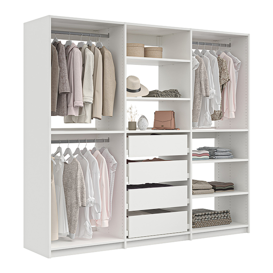
- Page 2 MILANO MODULAR WARDROBE On the following 2 pages you’ll see all the options you can place in your MILANO base units First we’ll start off by building the base units. Than for the Interior options, refer to the corosponding manuals for...
- Page 3 Assembly and Installation Manual Doors Options for 30” Wide Towers Mirror Slab Shaker Hanging Shelves Shoe Adjustable Double Tall Interior Options Drawer Pack Chest of Drawers Cubby Over Chest Cubby Insert...
- Page 4 Assembly and Installation Manual Doors Mirror Slab Shaker Options for 15” Wide Towers Double Tall Adjustable hanging hanging shelves...
- Page 5 Assembly and Installation Manual Table Of Contents Product Information Safety Warnings Assembly Preparation 8-11 Assembly Instructions 12-32...
-
Page 6: Safety Warnings
Assembly and Installation Manual Safety Warnings this product is intended for floor use only and not for wall mount use. Serious or fatal crushing injuries can occur WARNING from furniture tip-over. Serious or fatal crushing injuries To help prevent tip over: can occur from furniture tip-over. -
Page 7: Weight Capacity/Care Instructions
Assembly and Installation Manual Assembly and Installation Manual Weight capacity/Care instructions WARNING: This unit has been designed to support the maximun loads shown. Exceeding these load limits could cause sagging, instability, product collapse, and/or serious injury. WARNING: Please ensure that all the objects are removed before moving the assembled unit. The unit must be lifted by more than one person, not dragged or pushed. -
Page 8: Congratulations On Your Purchase
Good luck! (though we’re confident you won’t need it!) The Milano Installation Process Will Be Broken Down Into 2 Simple Steps 1: Building and installing the base units Single Unit (figure 1) or Combined Units (figure 2) -
Page 9: Before You Begin
Assembly and Installation Manual BEFORE YOU BEGIN 1. Check for damaged or missing parts. Call 844-969-4247 or Email customer service support@modularclosets.com, for help or to order miss- ing supplies. 2. Use the carton as a working surface to prevent product damage during assembly. 3. -
Page 10: Exploded Diagram
Assembly and Installation Manual Exploded diagram ITEM DESCRIPTION QUANTITY Right/Left side panel Shared Side Panel Fixed Shelf Top back cleat Toe Kick Back Cleat for combined unit... - Page 11 Assembly and Installation Manual Packaging and Hardware Box 1 MIL-SPP-84H22D-WHL Box 2 30” MIL-SRP30-22D-WHL (H14) x 2 15“ Closet rod MIL-SRP15-22D-WHL (H1) x 14 (H2) x 16 (H3) x 30 (H4) x 2 (H5) x 12 (H6) x 4 (H7) x 4 metel screw 3/8”...
- Page 12 Assembly and Installation Manual Step 1 Insert rafix into 2 fixed shelves ( ) and the toekick ( Box 2 rafix housing Step 2 Insert wedgefix into the remaining 1 fixed shelf ( ) and 2 cleats ( wedgefix F x2...
- Page 13 Assembly and Installation Manual Step 3 Install the connecting brackets into the 2 side panels ( ) and the top back cleat ( (H5) x 12 (H8) x 1 (H9) x 1 3/8” flat-head left-right left-right screw (H5) x 12 (H8) x 1 (H9) x 1 (H5) x 12...
- Page 14 Assembly and Installation Manual Step 4 Drill the metal screw dowels into the side panels (H3) x 30 metal screw dowel Right Left When inserting a tall hanging unit - Insert the 3 horizontal dowels on row 12 from the top 3 2 1 Instead of row 35, on the right and left panels Great you made it this far! Hope everthing is going good!
- Page 15 Assembly and Installation Manual Step 5 - Mounting prep Drill pilot holes into the wall using a Stud finder*, using the top back cleat ( ) as a template, and stop as soon as you hit the wall Use a tape measure to configure location as pictured below - 84.25” or 214 cm. (Height of the side panels) If using sheet rock put anchors in to the hole in the wall (H12) x 2...
- Page 16 Assembly and Installation Manual Introduction To The Mounting / Installation Process Your MILANO WARDROBE can be installed 2 ways. FIGURE A Without moldings (baseboard) - For a flush look straight against the wall FIGURE B With moldings (baseboard) - If your room has moldings, you don’t have to remove the moldings.
- Page 17 Assembly and Installation Manual Step 6 Drill / Drive in the screws through the top back cleat ( ) all the way into the wall (H6) x 2 (H13) x 2 washer 2”3/8 screw TC Now skip to step 8...
- Page 18 Assembly and Installation Manual Step 7 Drill / Drive in the screws through the top back cleat ( ) all the way into the wall with the spacer (H6) x 2 (H7) x 2 (H13) x 2 washer 2”3/8 screw TC spacer...
- Page 19 Assembly and Installation Manual Step 8 Hang left side panel ( ) onto back top cleat ( Left...
- Page 20 Assembly and Installation Manual Combined units Single unit Combined Units Continue to step 9 Skip to step 11...
- Page 21 Assembly and Installation Manual Step 9a Open box 3 and drill in the side connecting bracket on the shared sidepanel ( (H5) x 3 (H9) x 1 3/8” flat-head left screw side connecting bracket Pack 03 Step 9b Drill in the metal srew dowels on the shared sidepanel ( (H3) x 30 (H3) x 15 metal screw...
- Page 22 Assembly and Installation Manual Step 10a Flip over shared sidepanel and drill right side bracket into shared sidepanel ( (H9) x 1 (H5) x 3 3/8” flat-head right side screw connecting bracket Step 10b Drill in the metal srew dowels on the shared sidepanel ( (H3) x 30 (H3) x 15 metal screw...
- Page 23 Assembly and Installation Manual Step 11 Connect side panel to top back cleat ( ) with brackets [when building combined units, connect shared sidepanel (...
- Page 24 Assembly and Installation Manual Step 12 Connect back cleats ( ) onto the panels - (simply click in the knock-in housing in the dowel as shown)
- Page 25 Assembly and Installation Manual Step 13 Connect toe kick ( ) on the bottom, and then insert a philips screw driver into the hole of the wedgefix housing and turn clockwise until toe kick is firmly attached (Repeat for all 4 housings as shown)
- Page 26 Assembly and Installation Manual Step 14 Use the leveling wedges to ensure the unit is stable (H4) x 2 leveling wedge...
- Page 27 Assembly and Installation Manual Mounting Cleat #2 Continue to step Continue to step...
- Page 28 Assembly and Installation Manual Step 15a Use a stud finder* to drill 2 pilot holes into the wall through the bottom cleat and stop when you hit the stud If using sheet rock put anchors in to the hole in the wall (H12) x 2 wall anchor Step 15b Drill / Drive in the screws through the bottom cleat ( ) all the way into the wall (H6) x 2 (H13) x 2 2”3/8 screw TC...
- Page 29 Assembly and Installation Manual Step 16a Use a stud finder* to drill 2 pilot holes into the wall through the middle cleat and stop when you hit the stud If using sheet rock put anchors in to the hole in the wall (H12) x 2 wall anchor Step 16b Drill / Drive in the screws through the middle cleat ( ) all the way into the wall (H6) x 2 (H7) x 2 (H13) x 2...
- Page 30 Assembly and Installation Manual Step 17 Insert and secure the fixed shelves Top 2 fixed shelves are inserted and then secured as shown Bottom fixed shelf is simply inserted as shown when building tall hanging simply place middle shelf higher up, where dowels were drilled...
- Page 31 Assembly and Installation Manual Step 18 Snap on the bracket cover (H10) x 1 bracket cover...
- Page 32 Assembly and Installation Manual Single Unit Assembly And Installation Is Now Complete! For multiple units: Simply repeat the above assembly process for the rest of the units Combined Units...
Need help?
Do you have a question about the MILANO and is the answer not in the manual?
Questions and answers